Lexus ES: Data Signal Circuit between Radio Receiver and Stereo Jack Adapter
DESCRIPTION
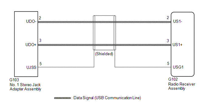
The No. 1 stereo jack adapter assembly sends the sound data signal or image data signal from a USB device to the radio receiver assembly via this circuit.
WIRING DIAGRAM
PROCEDURE
| 1. | CHECK HARNESS AND CONNECTOR (RADIO RECEIVER ASSEMBLY - NO. 1 STEREO JACK ADAPTER ASSEMBLY) |
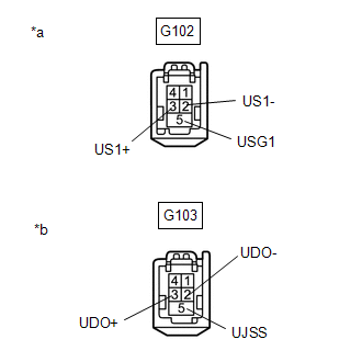
(a) Disconnect the G102 radio receiver assembly connector.
(b) Disconnect the G103 No. 1 stereo jack adapter assembly connector.
| (c) Measure the resistance according to the value(s) in the table below. Standard Resistance:
|
|
| OK |  | PROCEED TO NEXT SUSPECTED AREA SHOWN IN PROBLEM SYMPTOMS TABLE |
.gif)
| NG | | REPAIR OR REPLACE HARNESS OR CONNECTOR |
READ NEXT:
 Diagnostic Trouble Code Chart
DIAGNOSTIC TROUBLE CODE CHART Navigation System DTC No. Detection Item Link B1323 Lost Communication with Haptic Device B1324 Lost Communication with Meter B1325 Los
Disc cannot be Ejected
CAUTION / NOTICE / HINT NOTICE:
Depending on the parts that are replaced during vehicle inspection or maintenance, performing initialization, registration or calibration may be needed. Refer to Pre
Disc cannot be Inserted or is Ejected Right After Insertion
CAUTION / NOTICE / HINT NOTICE:
Depending on the parts that are replaced during vehicle inspection or maintenance, performing initialization, registration or calibration may be needed. Refer to Pre
SEE MORE:
Components
COMPONENTS ILLUSTRATION *1 FRONT LOWER NO. 1 FLOOR HEAT INSULATOR - - N*m (kgf*cm, ft.*lbf): Specified torque - - ILLUSTRATION *1 PROPELLER WITH CENTER BEARING SHAFT ASSEMBLY *2 CENTER NO. 2 SUPPORT BEARING WASHER Tightening torque for "Major areas involving
Precaution
PRECAUTION PRECAUTION FOR DISCONNECTING CABLE FROM NEGATIVE BATTERY TERMINAL NOTICE: When disconnecting the cable from the negative (-) battery terminal, initialize the following systems after the cable is reconnected. System Name See Procedure Lane Control System (for Gasoline Model)
