Lexus ES: No Response from ID BOX (B2789)
DESCRIPTION
This DTC is stored when LIN communication between the certification ECU (smart key ECU assembly) and ID code box (immobiliser code ECU) stops for 10 seconds or more.
| DTC No. | Detection Item | DTC Detection Condition | Trouble Area |
|---|---|---|---|
| B2789 | No Response from ID BOX | No communication between certification ECU (smart key ECU assembly) and ID code box (immobiliser code ECU) for 10 seconds or more. |
|
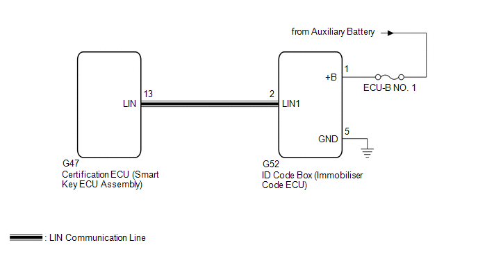
WIRING DIAGRAM
CAUTION / NOTICE / HINT
NOTICE:
- Inspect the fuses for circuits related to this system before performing the following procedure.
-
If the certification ECU (smart key ECU assembly) or ID code box (immobiliser code ECU) is replaced, refer to Registration.
Click here
.gif)
- When using the Techstream with the engine switch off, connect the Techstream to the DLC3 and turn a courtesy light switch on and off at intervals of 1.5 seconds or less until communication between the Techstream and the vehicle begins. Then select the vehicle type under manual mode and enter the following menus Body Electrical Smart Access. While using the Techstream, periodically turn a courtesy light switch on and off at intervals of 1.5 seconds or less to maintain communication between the Techstream and the vehicle.
PROCEDURE
| 1. | CHECK HARNESS AND CONNECTOR (CERTIFICATION ECU (SMART KEY ECU ASSEMBLY) - ID CODE BOX (IMMOBILISER CODE ECU)) |
(a) Disconnect the G47 certification ECU (smart key ECU assembly) connector.
(b) Disconnect the G52 ID code box (immobiliser code ECU) connector.
(c) Measure the resistance according to the value(s) in the table below.
NOTICE:
Make sure that each ECU is in sleep mode before performing the inspection. To enter sleep mode, turn the engine switch from on (IG) to off and wait for 180 seconds or more without operating any switches.
Standard Resistance:
| Tester Connection | Condition | Specified Condition |
|---|---|---|
| G47-13 (LIN) - G52-2 (LIN) | Engine switch off | Below 1 Ω |
| G47-13 (LIN) or G52-2 (LIN) - Body ground | Engine switch off | 10 kΩ or higher |
| NG | .gif) | REPAIR OR REPLACE HARNESS OR CONNECTOR |
|
.gif)
| 2. | CHECK HARNESS AND CONNECTOR (ID CODE BOX (IMMOBILISER CODE ECU) - BATTERY, BODY GROUND) |
(a) Measure the voltage according to the value(s) in the table below.
Standard Voltage:
| Tester Connection | Condition | Specified Condition |
|---|---|---|
| G52-1 (+B) - G52-5 (GND) | Always | 11 to 14 V |
(b) Measure the resistance according to the value(s) in the table below.
Standard Resistance:
| Tester Connection | Condition | Specified Condition |
|---|---|---|
| G52-5 (GND) - Body ground | Always | Below 1 Ω |
| NG | | REPAIR OR REPLACE HARNESS OR CONNECTOR |
|
| 3. | REPLACE ID CODE BOX (IMMOBILISER CODE ECU) |
(a) Replace the ID code box (immobiliser code ECU).
Click here
|
| 4. | REGISTER ECU CODE REGISTRATION |
(a) Register the recognition codes in the ECUs.
Click here
|
| 5. | CHECK FOR DTC |
(a) Clear the DTCs.
Click here
(b) Recheck for DTCs.
Body Electrical > Smart Access > Trouble CodesOK:
DTC B2789 is not output.
| OK | | END (ID CODE BOX (IMMOBILISER CODE ECU) WAS DEFECTIVE) |
| NG | | REPLACE CERTIFICATION ECU (SMART KEY ECU ASSEMBLY) |
READ NEXT:
 No Response from Steering Lock ECU (B2786)
DESCRIPTION This DTC is stored when LIN communication between the certification ECU (smart key ECU assembly) and steering lock ECU (steering lock actuator or upper bracket assembly) stops for 10 secon
Communication Malfunction between ECUs Connected by LIN (B2785)
DESCRIPTION If the certification ECU (smart key ECU assembly) detects a communication error with an ECU connected to the certification bus lines for 7 seconds or more, DTC B2785 will be stored. DTC
LIN Communication Bus Malfunction (B2325)
DESCRIPTION If the main body ECU (multiplex network body ECU) detects a communication error with an ECU connected to the door bus lines for 8 seconds or more, DTC B2325 will be stored. DTC No. De
SEE MORE:
Hybrid/EV Battery Discharge Control Malfunction (P300000)
DESCRIPTION The hybrid vehicle control ECU alerts the driver and performs fail-safe control based on error signals received from the battery voltage sensor. This DTC is stored when the SOC (state of charge) of the HV battery has dropped excessively as a result of leaving shift lever in N, running ou
Airbag Signal Signal Plausibility Failure (B15C464)
DESCRIPTION If the DCM (telematics transceiver) detects an error in communication between the DCM (telematics transceiver) and the airbag ECU assembly as a result of the DCM (telematics transceiver) self check, this DTC will be set. DTC No. Detection Item DTC Detection Condition Trouble Are
