Lexus ES: Wiper Motor Power Source Circuit
DESCRIPTION
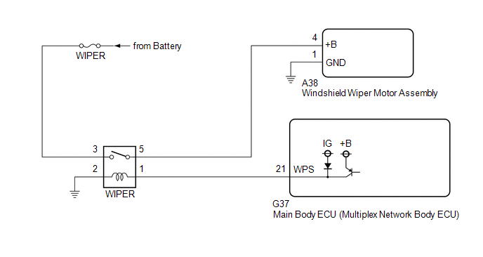
This circuit is the power source circuit for the windshield wiper motor assembly.
WIRING DIAGRAM
CAUTION / NOTICE / HINT
NOTICE:
- Inspect the fuses of circuits related to this system before performing the following procedure.
-
Before replacing the main body ECU (multiplex network body ECU), refer to Registration.
Click here
.gif)
PROCEDURE
| 1. | READ VALUE USING TECHSTREAM |
(a) Connect the Techstream to the DLC3.
(b) Turn the engine switch on (IG).
(c) Turn the Techstream on.
(d) Enter the following menus: Body Electrical / Wiper / Data List.
(e) Read the Data List according to the display on the Techstream.
Body Electrical > Wiper > Data List| Tester Display | Measurement Item | Range | Normal Condition | Diagnostic Note |
|---|---|---|---|---|
| Motor Power Supply Voltage | Front wiper motor assembly supply voltage status | Min.: 0 V Max.: 63 V | Almost the same as actual windshield wiper motor assembly voltage | - |
| Tester Display |
|---|
| Motor Power Supply Voltage |
OK:
The Techstream display is normal.
| OK | .gif) | PROCEED TO NEXT SUSPECTED AREA SHOWN IN PROBLEM SYMPTOMS TABLE |
|
.gif)
| 2. | CHECK HARNESS AND CONNECTOR (WINDSHIELD WIPER MOTOR ASSEMBLY - BODY GROUND) |
(a) Disconnect the A38 windshield wiper motor assembly connector.
(b) Measure the resistance according to the value(s) in the table below.
Standard Resistance:
| Tester Connection | Condition | Specified Condition |
|---|---|---|
| A38-1 (GND) - Body ground | Always | Below 1 Ω |
| NG | | REPAIR OR REPLACE HARNESS OR CONNECTOR |
|
| 3. | CHECK HARNESS AND CONNECTOR (POWER SOURCE - WINDSHIELD WIPER MOTOR ASSEMBLY) |
(a) Measure the voltage according to the value(s) in the table below.
Standard Voltage:
| Tester Connection | Condition | Specified Condition |
|---|---|---|
| A38-4 (+B) - Body ground | Engine switch on (IG) | 11 to 14 V |
| Less than approximately 60 seconds after engine switch turned off | 11 to 14 V | |
| Approximately 60 seconds after engine switch turned off | Below 1 V |
| OK | | REPLACE WINDSHIELD WIPER MOTOR ASSEMBLY |
|
| 4. | INSPECT WIPER RELAY |
(a) Inspect the WIPER relay.
Click here
| NG | | REPLACE WINDSHIELD WIPER RELAY |
|
| 5. | CHECK HARNESS AND CONNECTOR (POWER SOURCE - WIPER RELAY) |
(a) Measure the voltage according to the value(s) in the table below.
Standard Voltage:
| Tester Connection | Condition | Specified Condition |
|---|---|---|
| 3 (WIPER relay) - Body ground | Always | 11 to 14 V |
| NG | | REPAIR OR REPLACE HARNESS OR CONNECTOR |
|
| 6. | CHECK HARNESS AND CONNECTOR (WIPER RELAY - BODY GROUND) |
(a) Measure the resistance according to the value(s) in the table below.
Standard Resistance:
| Tester Connection | Condition | Specified Condition |
|---|---|---|
| 2 (WIPER relay) - Body ground | Always | Below 1 Ω |
| NG | | REPAIR OR REPLACE HARNESS OR CONNECTOR |
|
| 7. | CHECK HARNESS AND CONNECTOR (WIPER RELAY - WINDSHIELD WIPER MOTOR ASSEMBLY) |
(a) Measure the resistance according to the value(s) in the table below.
Standard Resistance:
| Tester Connection | Condition | Specified Condition |
|---|---|---|
| 5 (WIPER relay) - A38-4 (+B) | Always | Below 1 Ω |
| 5 (WIPER relay) or A38-4 (+B) - Body ground | Always | 10 kΩ or higher |
| NG | | REPAIR OR REPLACE HARNESS OR CONNECTOR |
|
| 8. | CHECK HARNESS AND CONNECTOR (WIPER RELAY - MAIN BODY ECU (MULTIPLEX NETWORK BODY ECU)) |
(a) Disconnect the G37 main body ECU (multiplex network body ECU) connector.
(b) Measure the resistance according to the value(s) in the table below.
Standard Resistance:
| Tester Connection | Condition | Specified Condition |
|---|---|---|
| 1 (WIPER relay) - G37-21 (WPS) | Always | Below 1 Ω |
| 1 (WIPER relay) or G37-21 (WPS) - Body ground | Always | 10 kΩ or higher |
| OK | | REPLACE MAIN BODY ECU (MULTIPLEX NETWORK BODY ECU) |
| NG | | REPAIR OR REPLACE HARNESS OR CONNECTOR |
READ NEXT:
 Wiper and Washer Switch Circuit
DESCRIPTION The condition of the windshield wiper switch assembly is detected and sent to the steering sensor in this circuit. WIRING DIAGRAM PROCEDURE 1. READ VALUE USING TECHSTREAM (a) Con
Washer Motor Circuit
DESCRIPTION When the windshield washer motor and pump assembly receives signals from the windshield wiper switch assembly it operates to spray washer fluid from the washer nozzle sub-assemblies. WIRIN
Washer Fluid Level Warning Switch Circuit
DESCRIPTION When the washer fluid level is lower than a certain level, a warning message is displayed on the combination meter assembly. WIRING DIAGRAM PROCEDURE 1. READ VALUE USING TECHSTREAM
SEE MORE:
Internal Control Module Software Incompatibility Invalid/Incompatible Software Component (U030057)
DESCRIPTION If the vehicle information stored in the forward recognition camera does not match the vehicle information sent from the hybrid vehicle control ECU, the forward recognition camera stores DTC U030057. DTC No. Detection Item DTC Detection Condition Trouble Area MIL DTC Output
Installation
INSTALLATION CAUTION / NOTICE / HINT NOTICE: This procedure includes the installation of small-head bolts. Refer to Small-Head Bolts of Basic Repair Hint to identify the small-head bolts. Click here PROCEDURE 1. INSTALL CAM TIMING CONTROL MOTOR O-RING (a) Install a new cam timing control motor
