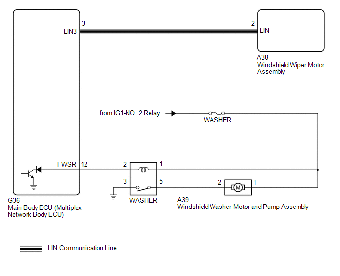
Lexus ES: Washer Motor Circuit
DESCRIPTION
When the windshield washer motor and pump assembly receives signals from the windshield wiper switch assembly it operates to spray washer fluid from the washer nozzle sub-assemblies.
WIRING DIAGRAM
CAUTION / NOTICE / HINT
NOTICE:
- Inspect the fuses for circuits related to this system before performing the following procedure.
-
Before replacing the main body ECU (multiplex network body ECU), refer to Registration.
Click here
.gif)
PROCEDURE
| 1. | PERFORM ACTIVE TEST USING TECHSTREAM |
(a) Connect the Techstream to the DLC3.
(b) Turn the engine switch on (IG).
(c) Turn the Techstream on.
(d) Enter following menus: Body Electrical / Main Body / Active Test.
(e) Perform the Active Test according to the display on the Techstream.
Body Electrical > Main Body > Active Test| Tester Display | Measurement Item | Control Range | Diagnostic Note |
|---|---|---|---|
| Front Washer Relay | Function to operate the windshield washer motor and pump assembly | OFF or ON | - |
| Tester Display |
|---|
| Front Washer Relay |
OK:
Windshield washer motor and pump assembly operates normally.
| OK | .gif) | PROCEED TO NEXT SUSPECTED AREA SHOWN IN PROBLEM SYMPTOMS TABLE |
|
.gif)
| 2. | INSPECT WINDSHIELD WASHER MOTOR AND PUMP ASSEMBLY |
(a) Remove the windshield washer motor and pump assembly.
Click here
(b) Inspect the windshield washer motor and pump assembly.
Click here
| NG | | REPLACE WINDSHIELD WASHER MOTOR AND PUMP ASSEMBLY |
|
| 3. | INSPECT WASHER RELAY |
(a) Inspect the WASHER relay.
Click here
| NG | | REPLACE WASHER RELAY |
|
| 4. | CHECK HARNESS AND CONNECTOR (POWER SOURCE - WASHER RELAY) |
(a) Measure the voltage according to the value(s) in the table below.
Standard Voltage:
| Tester Connection | Condition | Specified Condition |
|---|---|---|
| 1 (WASHER relay) - Body ground | Engine switch off | Below 1 V |
| Engine switch on (IG) | 11 to 14 V |
| NG | | REPAIR OR REPLACE HARNESS OR CONNECTOR |
|
| 5. | CHECK HARNESS AND CONNECTOR (POWER SOURCE - WINDSHIELD WASHER MOTOR AND PUMP ASSEMBLY) |
(a) Measure the voltage according to the value(s) in the table below.
Standard Voltage:
| Tester Connection | Condition | Specified Condition |
|---|---|---|
| A39-1 - Body ground | Engine switch off | Below 1 V |
| Engine switch on (IG) | 11 to 14 V |
| NG | | REPAIR OR REPLACE HARNESS OR CONNECTOR |
|
| 6. | CHECK HARNESS AND CONNECTOR (WASHER RELAY - WINDSHIELD WASHER MOTOR AND PUMP ASSEMBLY) |
(a) Measure the resistance according to the value(s) in the table below.
Standard Resistance:
| Tester Connection | Condition | Specified Condition |
|---|---|---|
| 5 (WASHER relay) - A39-2 | Always | Below 1 Ω |
| 5 (WASHER relay) or A39-2 - Body ground | Always | 10 kΩ or higher |
| NG | | REPAIR OR REPLACE HARNESS OR CONNECTOR |
|
| 7. | CHECK HARNESS AND CONNECTOR (WASHER RELAY - BODY GROUND) |
(a) Measure the resistance according to the value(s) in the table below.
Standard Resistance:
| Tester Connection | Condition | Specified Condition |
|---|---|---|
| 3 (WASHER relay) - Body ground | Always | Below 1 Ω |
| NG | | REPAIR OR REPLACE HARNESS OR CONNECTOR |
|
| 8. | CHECK HARNESS AND CONNECTOR (MAIN BODY ECU (MULTIPLEX NETWORK BODY ECU) - WASHER RELAY) |
(a) Disconnect the G36 main body ECU (multiplex network body ECU) connector.
(b) Measure the resistance according to the value(s) in the table below.
Standard Resistance:
| Tester Connection | Condition | Specified Condition |
|---|---|---|
| G36-12 (FWSR) - 2 (WASHER relay) | Always | Below 1 Ω |
| G36-12 (FWSR) or 2 (WASHER relay) - Body ground | Always | 10 kΩ or higher |
| OK | | REPLACE MAIN BODY ECU (MULTIPLEX NETWORK BODY ECU) |
| NG | | REPAIR OR REPLACE HARNESS OR CONNECTOR |
READ NEXT:
 Washer Fluid Level Warning Switch Circuit
DESCRIPTION When the washer fluid level is lower than a certain level, a warning message is displayed on the combination meter assembly. WIRING DIAGRAM PROCEDURE 1. READ VALUE USING TECHSTREAM
Precaution
PRECAUTION PRECAUTION FOR DISCONNECTING CABLE FROM NEGATIVE AUXILIARY BATTERY TERMINAL NOTICE: When disconnecting the cable from the negative (-) auxiliary battery terminal, initialize the following s
SEE MORE:
Disassembly
DISASSEMBLY PROCEDURE 1. REMOVE KICK DOOR CONTROL SENSOR WITH BRACKET (w/ Hands Free Power Trunk Lid) Click here 2. REMOVE REAR CENTER ULTRASONIC SENSOR (w/ Parking Support Alert System) Click here HINT: Use the same procedure for the RH side and LH side. 3. REMOVE REAR CORNER ULTRASONIC SENS
Horn
ComponentsCOMPONENTS ILLUSTRATION *1 COOL AIR INTAKE DUCT SEAL *2 HIGH PITCHED HORN ASSEMBLY *3 LOW PITCHED HORN ASSEMBLY - - N*m (kgf*cm, ft.*lbf): Specified torque - - RemovalREMOVAL PROCEDURE 1. REMOVE COOL AIR INTAKE DUCT SEAL Click here 2. REMOVE HIGH PITC
