Lexus ES: Washer Fluid Level Warning Switch Circuit
DESCRIPTION
When the washer fluid level is lower than a certain level, a warning message is displayed on the combination meter assembly.
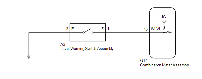
WIRING DIAGRAM
PROCEDURE
| 1. | READ VALUE USING TECHSTREAM |
(a) Connect the Techstream to the DLC3.
(b) Turn the engine switch on (IG).
(c) Turn the Techstream on.
(d) Enter the following menus: Body Electrical / Combination Meter / Data List.
(e) Read the Data List according to the display on the Techstream.
Body Electrical > Combination Meter > Data List| Tester Display | Measurement Item | Range | Normal Condition | Diagnostic Note |
|---|---|---|---|---|
| Washer Level Warning Switch | Washer fluid level warning switch | OFF or ON | OFF: Washer fluid level not low ON: Washer fluid level low | - |
| Tester Display |
|---|
| Washer Level Warning Switch |
OK:
The Techstream display changes correctly in response to the washer fluid level.
| OK | .gif) | REPLACE COMBINATION METER ASSEMBLY |
|
.gif)
| 2. | INSPECT LEVEL WARNING SWITCH ASSEMBLY |
(a) Remove the level warning switch assembly.
Click here .gif)
(b) Inspect the level warning switch assembly.
Click here
| NG | | REPLACE LEVEL WARNING SWITCH ASSEMBLY |
|
| 3. | CHECK HARNESS AND CONNECTOR (LEVEL WARNING SWITCH ASSEMBLY - COMBINATION METER ASSEMBLY) |
(a) Disconnect the G17 combination meter assembly connector.
(b) Measure the resistance according to the value(s) in the table below.
Standard Resistance:
| Tester Connection | Condition | Specified Condition |
|---|---|---|
| A3-1 (S) - G17-16 (WLVL) | Always | Below 1 Ω |
| A3-1 (S) or G17-16 (WLVL) - Body ground | Always | 10 kΩ or higher |
| NG | | REPAIR OR REPLACE HARNESS OR CONNECTOR |
|
| 4. | CHECK HARNESS AND CONNECTOR (LEVEL WARNING SWITCH ASSEMBLY - BODY GROUND) |
(a) Measure the resistance according to the value(s) in the table below.
Standard Resistance:
| Tester Connection | Condition | Specified Condition |
|---|---|---|
| A3-2 (E) - Body ground | Always | Below 1 Ω |
| OK | | REPLACE COMBINATION METER ASSEMBLY |
| NG | | REPAIR OR REPLACE HARNESS OR CONNECTOR |
READ NEXT:
 Precaution
PRECAUTION PRECAUTION FOR DISCONNECTING CABLE FROM NEGATIVE AUXILIARY BATTERY TERMINAL NOTICE: When disconnecting the cable from the negative (-) auxiliary battery terminal, initialize the following s
Parts Location
PARTS LOCATION ILLUSTRATION *A w/ Auto Wiper System - - *1 WINDSHIELD WIPER MOTOR ASSEMBLY *2 RAIN SENSOR *3 LEVEL WARNING SWITCH ASSEMBLY *4 WINDSHIELD WASHER MOTOR AND
SEE MORE:
Reassembly
REASSEMBLY PROCEDURE 1. INSTALL VACUUM WARNING SWITCH ASSEMBLY (a) Install a new check valve grommet to the brake booster assembly. (b) Install the vacuum warning switch assembly to the brake booster assembly as shown in the illustration. *a 30° +/- 20° Up 2. INSTALL BRAKE VACUUM C
Inspection
INSPECTION PROCEDURE 1. INSPECT OUTER MIRROR RH (a) Check the outer mirror heater operation. (1) Measure the resistance according to the value(s) in the table below. Standard Resistance: Tester Connection Condition Specified Condition 1 - 2 25°C (77°F) 3.8 to 5.8 Ω If the re
