Lexus ES: Transmission Range Sensor "A" Circuit (PRNDL Input) Signal Compare Failure (P070562)
DESCRIPTION
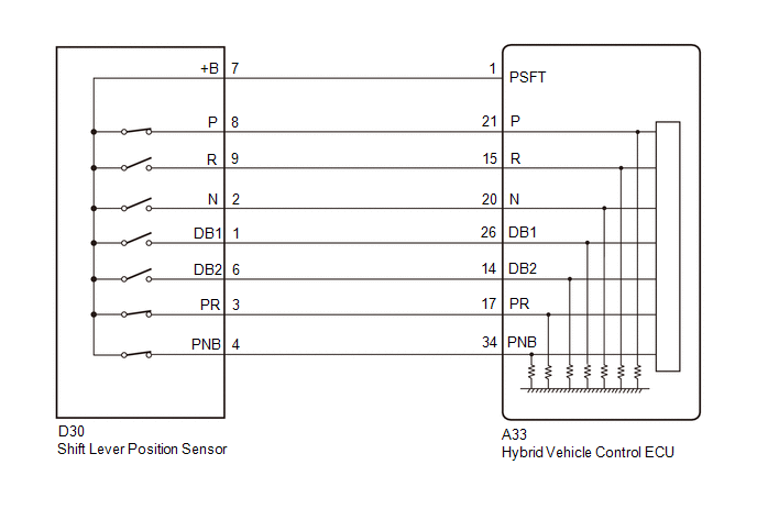
The shift lever position sensor sends 7 different switch signals to the hybrid vehicle control ECU. The hybrid vehicle control ECU uses these signals to detect the shift lever position (P, R, N or D). The hybrid vehicle control ECU also uses this information to determine the intended direction of travel (forward or reverse).
| DTC No. | Detection Item | DTC Detection Condition | Trouble Area | MIL | Warning Indicate |
|---|---|---|---|---|---|
| P070562 | Transmission Range Sensor "A" Circuit (PRNDL Input) Signal Compare Failure | Shift sensor circuit malfunction (abnormal pattern) A malfunction in the P, R, N or D circuit is detected based on the shift sensor input pattern. (1 trip detection logic) |
| Does not come on | Master Warning Light: Comes on |
| DTC No. | Data List |
|---|---|
| P070562 |
|
CONFIRMATION DRIVING PATTERN
HINT:
After repair has been completed, clear the DTCs and then check that the vehicle has returned to normal by performing the following All Readiness check procedure.
Click here .gif)
- Connect the Techstream to the DLC3.
- Turn the power switch on (IG) and turn the Techstream on.
- Clear the DTCs (even if no DTCs are stored, perform the clear DTC procedure).
- Turn the power switch off and wait for 2 minutes or more.
- Turn the power switch on (IG) and turn the Techstream on.
- Slowly move the shift lever from P to S then back to P.
- Enter the following menus: Powertrain / Hybrid Control / Utility / All Readiness.
-
Check the DTC judgment result.
HINT:
- If the judgment result shows NORMAL, the system is normal.
- If the judgment result shows ABNORMAL, the system has a malfunction.
- If the judgment result shows INCOMPLETE or N/A, perform driving pattern again.
WIRING DIAGRAM
PROCEDURE
| 1. | READ VALUE USING TECHSTREAM (SHIFT POSITION SENSOR) |
(a) Connect the Techstream to the DLC3.
(b) Turn the power switch on (IG).
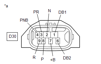
(c) Enter the following menus: Powertrain / Hybrid Control / Data List / Shift Position Sensor (PNB), Shift Position Sensor (PR), Shift Position Sensor (DB1), Shift Position Sensor (DB2), Shift Position Sensor (N), Shift Position Sensor (R) and Shift Position Sensor (P).
(d) While slowly moving the shift lever from P to S, then back to P, read the Data List (Shift Position Sensor) displayed on the Techstream.
Powertrain > Hybrid Control > Data List| Tester Display |
|---|
| Shift Position Sensor (PNB) |
| Shift Position Sensor (PR) |
| Shift Position Sensor (DB1) |
| Shift Position Sensor (DB2) |
| Shift Position Sensor (N) |
| Shift Position Sensor (R) |
| Shift Position Sensor (P) |
HINT:
Be sure to move the shift lever slowly.
Standard:
| Data List | Shift Position | |||
| P | R | N | D or S | |
| Shift Position Sensor (P) | ON | OFF | OFF | OFF |
| Shift Position Sensor (R) | OFF | ON | OFF | OFF |
| Shift Position Sensor (PR) | ON | ON | OFF | OFF |
| Shift Position Sensor (N) | OFF | OFF | ON | OFF |
| Shift Position Sensor (DB1) | OFF | OFF | OFF | ON |
| Shift Position Sensor (DB2) | OFF | OFF | OFF | ON |
| Shift Position Sensor (PNB) | ON | OFF | ON | OFF |
(e) Check for DTCs.
Powertrain > Hybrid Control > Trouble CodesOK:
DTC P070562 is not output.
(f) Turn the power switch off.
| NG | .gif) | GO TO STEP 3 |
|
.gif)
| 2. | CHECK FOR INTERMITTENT PROBLEMS |
Click here
| OK | | REPLACE HYBRID VEHICLE CONTROL ECU |
| NG | | REPAIR OR REPLACE MALFUNCTIONING PARTS, COMPONENT AND AREA |
| 3. | INSPECT SHIFT LEVER POSITION SENSOR |
(a) Turn the power switch on (IG).
| (b) Measure the voltage according to the value(s) in the table below. Standard Voltage:
|
|
(c) Turn the power switch off.
| OK | | REPLACE HYBRID VEHICLE CONTROL ECU |
|
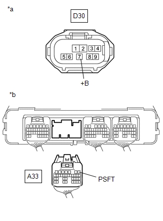
| 4. | CHECK HARNESS AND CONNECTOR (POWER SOURCE CIRCUIT) |
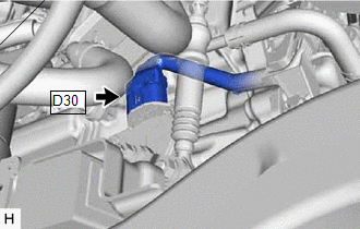
| (a) Disconnect the D30 shift lever position sensor connector. |
|
(b) Turn the power switch on (IG).
| (c) Measure the voltage according to the value(s) in the table below. Standard Voltage:
NOTICE: Turning the power switch on (IG) with the shift lever position sensor connector disconnected causes other DTCs to be stored. Clear the DTCs after performing this inspection. |
|
(d) Turn the power switch off.
(e) Reconnect the D30 shift lever position sensor connector.
| NG | | GO TO STEP 6 |
|
| 5. | INSPECT SHIFT LEVER POSITION SENSOR |
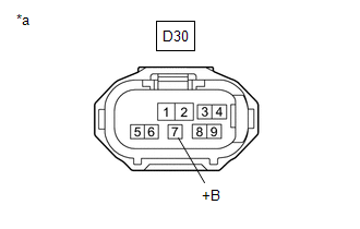
| (a) Disconnect the D30 shift lever position sensor connector. |
|
| (b) Measure the resistance according to the value(s) in the table below. Standard Resistance:
HINT: Terminals No. 5 on the component side connector is empty. |
|
(c) Reconnect the D30 shift lever position sensor connector.
| OK | | REPAIR OR REPLACE HARNESS OR CONNECTOR |
| NG | | REPLACE SHIFT LEVER POSITION SENSOR |
| 6. | CHECK HARNESS AND CONNECTOR (SHIFT LEVER POSITION SENSOR - HYBRID VEHICLE CONTROL ECU) |
(a) Disconnect the D30 shift lever position sensor connector.
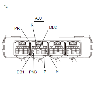
(b) Disconnect the A33 hybrid vehicle control ECU connector.
| (c) Measure the resistance according to the value(s) in the table below. Standard Resistance:
|
|
(d) Reconnect the A33 hybrid vehicle control ECU connector.
(e) Reconnect the D30 shift lever position sensor connector.
| OK | | REPLACE HYBRID VEHICLE CONTROL ECU |
| NG | | REPAIR OR REPLACE HARNESS OR CONNECTOR |
READ NEXT:
 High Voltage System Interlock Circuit Open (P0A0A13,P0A0A92)
DTC SUMMARY MALFUNCTION DESCRIPTION The hybrid vehicle control ECU detects that a safety device (interlock) is operated or that there is an open circuit in the detection circuit. (Even if an open circ
Drive Motor "A" Control Module Internal Electronic Failure (P0A1B49)
DESCRIPTION The MG ECU, which is built into the inverter with converter assembly, monitors its internal operation and will store DTCs if the system is malfunctioning. DTC No. Detection Item DTC
Drive Motor "A" Control Module Unexpected Operation (P0A1B94)
DTC SUMMARY MALFUNCTION DESCRIPTION The hybrid vehicle control ECU monitors the motor generator control ECU (MG ECU). The cause of this malfunction may be the following: Motor generator control ECU i
SEE MORE:
Headlight Beam Level Control Motor LH Lost Communication (B2424,B2425)
DESCRIPTION Each headlight ECU sub-assembly and headlight leveling motor communicate via LIN communication. The headlight leveling motor operates according to power supplied and automatic headlight beam level control signals from its respective headlight ECU sub-assembly and sends its operating stat
Lost Communication with Haptic Device (B1323,B1324,B1326)
DESCRIPTION These DTCs are stored when communication between the radio receiver assembly and remote touch (remote operation controller assembly), combination meter assembly or clock assembly is not possible. DTC No. Detection Item DTC Detection Condition Trouble Area B1323 Lost Commun
