Lexus ES: Headlight Beam Level Control Motor LH Lost Communication (B2424,B2425)
DESCRIPTION
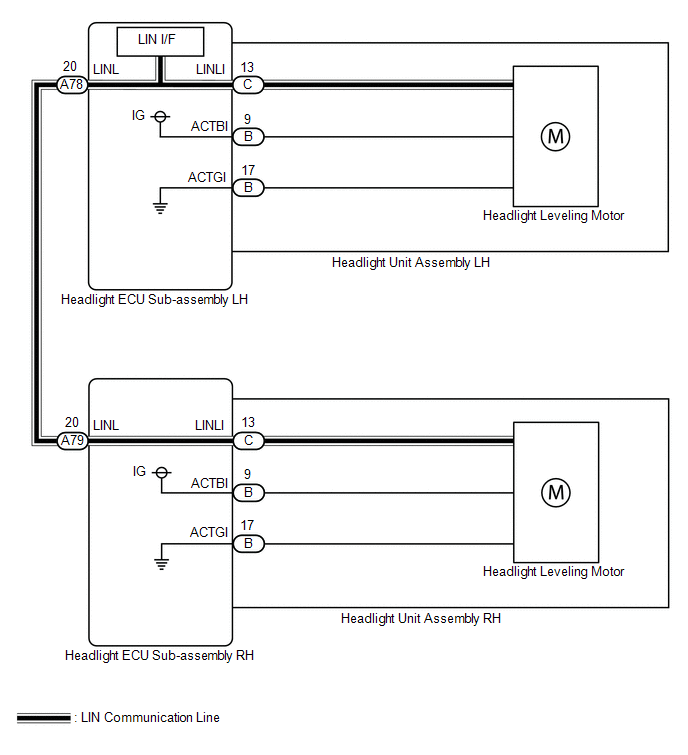
Each headlight ECU sub-assembly and headlight leveling motor communicate via LIN communication.
The headlight leveling motor operates according to power supplied and automatic headlight beam level control signals from its respective headlight ECU sub-assembly and sends its operating state to the headlight ECU sub-assembly.
| DTC No. | Detection Item | DTC Detection Condition | Trouble Area | DTC Output from |
|---|---|---|---|---|
| B2424 | Headlight Beam Level Control Motor LH Lost Communication |
|
| AFS |
| B2425 | Headlight Beam Level Control Motor RH Lost Communication |
|
| AFS |
WIRING DIAGRAM
CAUTION / NOTICE / HINT
NOTICE:
-
If the headlight ECU sub-assembly LH has been replaced, it is necessary to synchronize the vehicle information and initialize the headlight ECU sub-assembly LH.
Click here
.gif)
- When replacing the headlight ECU sub-assembly LH, always replace it with a new one. If a headlight ECU sub-assembly LH which was installed to another vehicle is used, the information stored in it will not match the information from the vehicle and a DTC may be stored.
PROCEDURE
| 1. | CLEAR DTC |
(a) Connect the Techstream to the DLC3.
(b) Turn the engine switch on (IG).
(c) Turn the Techstream on.
(d) Enter the following menus: Body Electrical / AFS / Trouble Codes.
(e) Clear the DTCs.
Body Electrical > AFS > Clear DTCs
|
.gif)
| 2. | CHECK FOR DTC |
(a) Connect the Techstream to the DLC3.
(b) Turn the engine switch on (IG).
(c) Wait 10 seconds or more.
(d) Turn the Techstream on.
(e) Enter the following menus: Body Electrical / AFS / Trouble Codes.
(f) Check for DTCs.
Body Electrical > AFS > Trouble CodesOK:
DTC B2424 and B2425 are not output.
| Result | Proceed to |
|---|---|
| OK | A |
| NG (DTC B2424 is output) | B |
| NG (DTC B2425 is output) | C |
| NG (DTC B2424 and B2425 are output) | D |
| A | .gif) | USE SIMULATION METHOD TO CHECK |
| C | | GO TO STEP 4 |
| D | | GO TO STEP 7 |
|
| 3. | INSPECT HEADLIGHT ECU SUB-ASSEMBLY LH |

| *a | Component without harness connected (Headlight ECU Sub-assembly LH) | - | - |
(a) Remove the headlight ECU sub-assembly LH.
Click here
(b) Measure the resistance according to the value(s) in the table below.
Standard Resistance:
| Tester Connection | Condition | Specified Condition |
|---|---|---|
| A78-20 (LINL) - C-13 (LINLI) | Always | Below 1 Ω |
| OK | | REPLACE HEADLIGHT UNIT ASSEMBLY LH |
| NG | | REPLACE HEADLIGHT ECU SUB-ASSEMBLY LH |
| 4. | CHECK HARNESS AND CONNECTOR (HEADLIGHT ECU SUB-ASSEMBLY LH - HEADLIGHT ECU SUB-ASSEMBLY RH) |
(a) Disconnect the A78 headlight ECU sub-assembly LH connector.
(b) Disconnect the A79 headlight ECU sub-assembly RH connector.
(c) Measure the resistance according to the value(s) in the table below.
Standard Resistance:
| Tester Connection | Condition | Specified Condition |
|---|---|---|
| A78-20 (LINL) - A79-20 (LINL) | Always | Below 1 Ω |
| NG | | REPAIR OR REPLACE HARNESS OR CONNECTOR |
|
| 5. | CHECK HEADLIGHT ECU SUB-ASSEMBLY LH (LINL TERMINAL SIGNAL OUTPUT) |
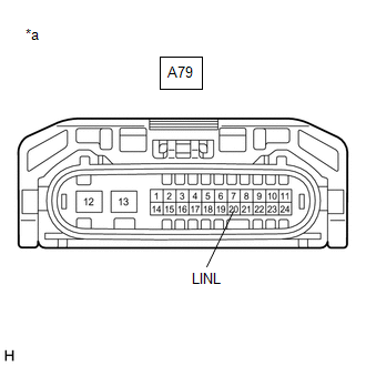
| *a | Front view of wire harness connector (to Headlight ECU Sub-assembly RH) |
(a) Connect the A78 headlight ECU sub-assembly LH connector.
(b) Using a Techstream, check the waveform.
OK:
| Tester Connection | Condition | Specified Condition |
|---|---|---|
| A79-20 (LINL) - Body ground | Engine switch on (IG) | Pulse generation |
| NG | | REPLACE HEADLIGHT ECU SUB-ASSEMBLY LH |
|
| 6. | INSPECT HEADLIGHT ECU SUB-ASSEMBLY RH |
| *a | Component without harness connected (Headlight ECU Sub-assembly RH) | - | - |
(a) Remove the headlight ECU sub-assembly RH.
Click here
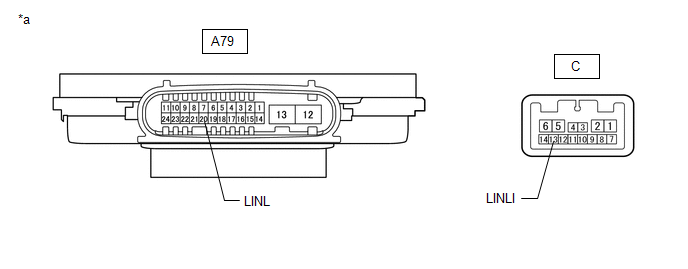
(b) Measure the resistance according to the value(s) in the table below.
Standard Resistance:
| Tester Connection | Condition | Specified Condition |
|---|---|---|
| A79-20 (LINL) - C-13 (LINLI) | Always | Below 1 Ω |
| OK | | REPLACE HEADLIGHT UNIT ASSEMBLY RH |
| NG | | REPLACE HEADLIGHT ECU SUB-ASSEMBLY RH |
| 7. | CHECK HARNESS AND CONNECTOR (HEADLIGHT ECU SUB-ASSEMBLY LH - HEADLIGHT ECU SUB-ASSEMBLY RH) |
(a) Disconnect the A78 headlight ECU sub-assembly LH connector.
(b) Disconnect the A79 headlight ECU sub-assembly RH connector.
(c) Measure the resistance according to the value(s) in the table below.
Standard Resistance:
| Tester Connection | Condition | Specified Condition |
|---|---|---|
| A78-20 (LINL) or A79-20 (LINL) - Body ground | Always | 10 kΩ or higher |
| NG | | REPAIR OR REPLACE HARNESS OR CONNECTOR |
|
| 8. | CLEAR DTC |
(a) Connect the A78 headlight ECU sub-assembly LH connector.
(b) Connect the Techstream to the DLC3.
(c) Turn the engine switch on (IG).
(d) Turn the Techstream on.
(e) Enter the following menus: Body Electrical / AFS / Trouble Codes.
(f) Clear the DTCs.
Body Electrical > AFS > Clear DTCs
|
| 9. | CHECK FOR DTC |
(a) Connect the Techstream to the DLC3.
(b) Turn the engine switch on (IG).
(c) Wait 10 seconds or more.
(d) Turn the Techstream on.
(e) Enter the following menus: Body Electrical / AFS / Trouble Codes.
(f) Check for DTCs.
Body Electrical > AFS > Trouble Codes| Result | Proceed to |
|---|---|
| DTC B2425 is output | A |
| DTC B2424 and B2425 are output | B |
| B | | GO TO STEP 13 |
|
| 10. | CHECK HEADLIGHT ECU SUB-ASSEMBLY RH |
(a) Remove the headlight ECU sub-assembly RH.
Click here
(b) Connect the A79 headlight ECU sub-assembly RH connector.
|
| 11. | CLEAR DTC |
(a) Connect the Techstream to the DLC3.
(b) Turn the engine switch on (IG).
(c) Turn the Techstream on.
(d) Enter the following menus: Body Electrical / AFS / Trouble Codes.
(e) Clear the DTCs.
Body Electrical > AFS > Clear DTCs
|
| 12. | CHECK FOR DTC |
(a) Connect the Techstream to the DLC3.
(b) Turn the engine switch on (IG).
(c) Wait 10 seconds or more.
(d) Turn the Techstream on.
(e) Enter the following menus: Body Electrical / AFS / Trouble Codes.
(f) Check for DTCs.
Body Electrical > AFS > Trouble Codes| Result | Proceed to |
|---|---|
| DTC B2425 is output | A |
| DTC B2424 and B2425 are output | B |
| A | | REPLACE HEADLIGHT UNIT ASSEMBLY RH |
| B | | REPLACE HEADLIGHT ECU SUB-ASSEMBLY RH |
| 13. | CHECK HEADLIGHT ECU SUB-ASSEMBLY LH |
(a) Remove the headlight ECU sub-assembly LH.
Click here
(b) Connect the A78 headlight ECU sub-assembly LH connector.
(c) Connect the A79 headlight ECU sub-assembly RH connector.
|
| 14. | CLEAR DTC |
(a) Connect the Techstream to the DLC3.
(b) Turn the engine switch on (IG).
(c) Turn the Techstream on.
(d) Enter the following menus: Body Electrical / AFS / Trouble Codes.
(e) Clear the DTCs.
Body Electrical > AFS > Clear DTCs
|
| 15. | CHECK FOR DTC |
(a) Connect the Techstream to the DLC3.
(b) Turn the engine switch on (IG).
(c) Wait 10 seconds or more.
(d) Turn the Techstream on.
(e) Enter the following menus: Body Electrical / AFS / Trouble Codes.
(f) Check for DTCs.
Body Electrical > AFS > Trouble Codes| Result | Proceed to |
|---|---|
| DTC B2424 is output | A |
| DTC B2424 and B2425 are output | B |
| A | | REPLACE HEADLIGHT UNIT ASSEMBLY LH |
| B | | REPLACE HEADLIGHT ECU SUB-ASSEMBLY LH |
READ NEXT:
 Right Headlight ECU Malfunction (B242C,B242D)
DESCRIPTION The headlight ECU sub-assembly LH or headlight ECU sub-assembly RH stores a DTC if it detects an internal malfunction. for LED Type Turn Signal Light DTC No. Detection Item DTC Dete
Open in IG Circuit (B242E)
DESCRIPTION The headlight ECU sub-assembly operates using the power source voltage input from the IG terminal and ECUB terminal. The IG terminal power source voltage is supplied by turning the IG1-NO.
Open in B Power Line (B242F)
DESCRIPTION The headlight ECU sub-assembly operates using the power source voltage input from the IG terminal and ECUB terminal. The power source voltage of the ECUB terminal is supplied when the main
SEE MORE:
Speed Signal Malfunction (B15C2)
DESCRIPTION The navigation ECU receives a vehicle speed signal from the combination meter assembly and information from the navigation antenna assembly, and then adjusts the vehicle position on the map. The navigation ECU stores this DTC when the difference between the speed information that the nav
On-vehicle Inspection
ON-VEHICLE INSPECTION CAUTION / NOTICE / HINT CAUTION: To prevent injury due to contact with an operating V-ribbed belt or cooling fan, keep your hands and clothing away from the V-ribbed belt and cooling fans when working in the engine compartment with the engine running or the engine switch on (I
