Lexus ES: Television Camera (for Front)
Components
COMPONENTS
ILLUSTRATION
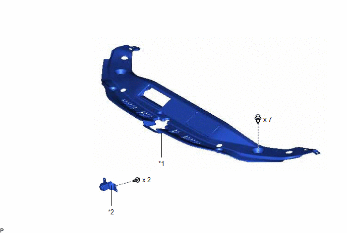
| *1 | COOL AIR INTAKE DUCT SEAL | *2 | FRONT TELEVISION CAMERA ASSEMBLY |
Installation
INSTALLATION
PROCEDURE
1. INSTALL FRONT TELEVISION CAMERA ASSEMBLY
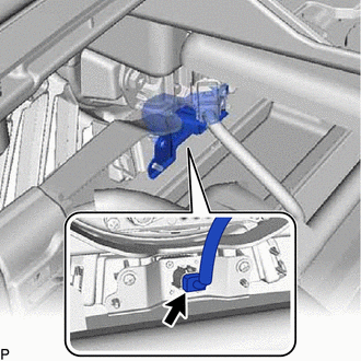
(a) Engage the 2 guides.
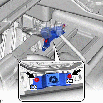
(b) Install the front television camera assembly with the 2 screws.
(c) Connect the connector.
2. INSTALL COOL AIR INTAKE DUCT SEAL
Click here .gif)
3. PERFORM CALIBRATION
for HV Model: Click here
for Gasoline Model: Click here
Removal
REMOVAL
CAUTION / NOTICE / HINT
The necessary procedures (adjustment, calibration, initialization, or registration) that must be performed after parts are removed and installed, or replaced during front television camera assembly removal/installation are shown below.
Necessary Procedure After Parts Removed/Installed/Replaced (for HV Model)| Replaced Part or Performed Procedure | Necessary Procedure | Effect/Inoperative Function When Necessary Procedures are not Performed | Link |
|---|---|---|---|
| Front television camera assembly | Front television camera view adjustment | Panoramic View Monitor System | |
| Replaced Part or Performed Procedure | Necessary Procedure | Effect/Inoperative Function When Necessary Procedures are not Performed | Link |
|---|---|---|---|
| Front television camera assembly | Front television camera view adjustment | Panoramic View Monitor System | |
PROCEDURE
1. REMOVE COOL AIR INTAKE DUCT SEAL
Click here .gif)
2. REMOVE FRONT TELEVISION CAMERA ASSEMBLY
| (a) Disconnect the connector. |
|
| (b) Remove the 2 screws. |
|
(c) Disengage the 2 guides to remove the front television camera assembly.
READ NEXT:
 Components
COMPONENTS ILLUSTRATION *1 OUTER MIRROR *2 OUTER MIRROR COVER ASSEMBLY *3 SIDE TELEVISION CAMERA ASSEMBLY *4 OUTER MIRROR TAPE *5 CAMERA CONNECTOR CLAMP - - ● Non
Installation
INSTALLATION CAUTION / NOTICE / HINT HINT:
Use the same procedure for the RH side and LH side.
The following procedure is for the LH side.
PROCEDURE 1. INSTALL SIDE TELEVISION CAMERA ASSEMBLY
SEE MORE:
Data Signal Circuit between Radio Receiver and Stereo Jack Adapter
DESCRIPTION The No. 1 stereo jack adapter assembly sends the sound data signal or image data signal from a USB device to the radio receiver assembly via this circuit. WIRING DIAGRAM PROCEDURE 1. CHECK HARNESS AND CONNECTOR (RADIO RECEIVER ASSEMBLY - NO. 1 STEREO JACK ADAPTER ASSEMBLY) (a)
Control Module Internal Temperature Sensor "A" Circuit Circuit Voltage Out of Range (C10001C,...,C1A961C)
DESCRIPTION When an internal malfunction is detected in the forward recognition camera, these DTCs are stored. DTC No. Detection Item DTC Detection Condition Trouble Area C10001C Control Module Internal Temperature Sensor "A" Circuit Circuit Voltage Out of Range A forward recognitio
