Lexus ES: Air Conditioning Amplifier Communication Stop Mode
DESCRIPTION
| Detection Item | Symptom | Trouble Area |
|---|---|---|
| Air Conditioning Amplifier Communication Stop Mode | Any of the following conditions are met:
|
|
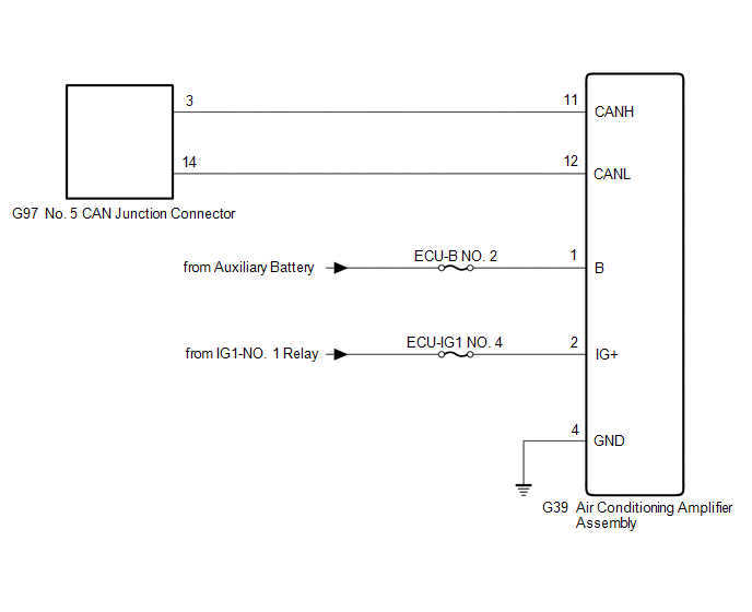
WIRING DIAGRAM
CAUTION / NOTICE / HINT
CAUTION:
When performing the confirmation driving pattern, obey all speed limits and traffic laws.
NOTICE:
-
Because the order of diagnosis is important to allow correct diagnosis, make sure to begin troubleshooting using How to Proceed with Troubleshooting when CAN communication system related DTCs are output.
Click here
.gif)
- Before measuring the resistance of the CAN bus, turn the power switch off and leave the vehicle for 1 minute or more without operating the key or any switches, or opening or closing the doors. After that, disconnect the cable from the negative (-) auxiliary battery terminal and leave the vehicle for 1 minute or more before measuring the resistance.
-
After turning the power switch off, waiting time may be required before disconnecting the cable from the negative (-) auxiliary battery terminal. Therefore, make sure to read the disconnecting the cable from the negative (-) auxiliary battery terminal notices before proceeding with work.
Click here
-
After performing repairs, perform the DTC check procedure and confirm that the DTCs are not output again.
DTC check procedure: Turn the power switch on (IG) and wait for 1 minute or more. Then operate the suspected malfunctioning system and drive the vehicle at 60 km/h (37 mph) or more for 5 minutes or more.
-
After the repair, perform the CAN bus check and check that all the ECUs and sensors connected to the CAN communication system are displayed as normal.
Click here
- Inspect the fuses for circuits related to this system before performing the following procedure.
HINT:
- Before disconnecting related connectors for inspection, push in on each connector body to check that the connector is not loose or disconnected.
- When a connector is disconnected, check that the terminals and connector body are not cracked, deformed or corroded.
PROCEDURE
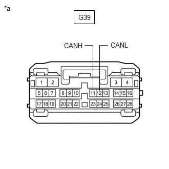
| 1. | CHECK FOR OPEN IN CAN BUS LINES (AIR CONDITIONING AMPLIFIER ASSEMBLY BRANCH LINE) |
(a) Disconnect the cable from the negative (-) auxiliary battery terminal.
(b) Disconnect the G39 air conditioning amplifier assembly connector.
| (c) Measure the resistance according to the value(s) in the table below. Standard Resistance:
|
|
| NG | .gif) | REPAIR OR REPLACE CAN BRANCH LINES OR CONNECTOR (AIR CONDITIONING AMPLIFIER ASSEMBLY) |
|
.gif)
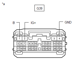
| 2. | CHECK HARNESS AND CONNECTOR (POWER SOURCE CIRCUIT) |
| (a) Measure the resistance according to the value(s) in the table below. Standard Resistance:
|
|
(b) Reconnect the cable to the negative (-) auxiliary battery terminal.
(c) Measure the voltage according to the value(s) in the table below.
Standard Voltage:
| Tester Connection | Condition | Specified Condition |
|---|---|---|
| G39-1 (B) - Body ground | Power switch off | 11 to 14 V |
| G39-2 (IG+) - Body ground | Power switch on (IG) | 11 to 14 V |
| OK | | REPLACE AIR CONDITIONING AMPLIFIER ASSEMBLY |
| NG | | REPAIR OR REPLACE HARNESS OR CONNECTOR (POWER SOURCE CIRCUIT) |
READ NEXT:
 Clearance Warning ECU Communication Stop Mode
DESCRIPTION Detection Item Symptom Trouble Area Clearance Warning ECU Communication Stop Mode Any of the following conditions are met:
Communication stop for "Clearance Warning (Intuit
Skid Control ECU Communication Stop Mode
DESCRIPTION Detection Item Symptom Trouble Area Skid Control ECU Communication Stop Mode Any of the following conditions are met:
Communication stop for "Skid Control (ABS/VSC/TRAC)" i
Hybrid Vehicle Control ECU Communication Stop Mode
DESCRIPTION Detection Item Symptom Trouble Area Hybrid Vehicle Control ECU Communication Stop Mode Any of the following conditions are met:
Communication stop for "Hybrid Vehicle Contr
SEE MORE:
Engine Oil Pressure Sensor/Switch "A" Signal Stuck High (P052024,P05202A)
DESCRIPTION Refer to DTC P052012. Click here DTC No. Detection Item DTC Detection Condition Trouble Area MIL Memory Note P052024 Engine Oil Pressure Sensor/Switch "A" Signal Stuck High The oil pressure sensor output voltage is higher than the threshold value (1 trip detectio
Installation
INSTALLATION CAUTION / NOTICE / HINT CAUTION: The engine assembly with transaxle is very heavy. Be sure to follow the procedure described in the repair manual, or the engine lifter may suddenly drop or the engine assembly with transaxle may fall off the engine lifter. PROCEDURE 1. INSTALL REAR NO. 2
