Lexus ES: System Diagram
SYSTEM DIAGRAM
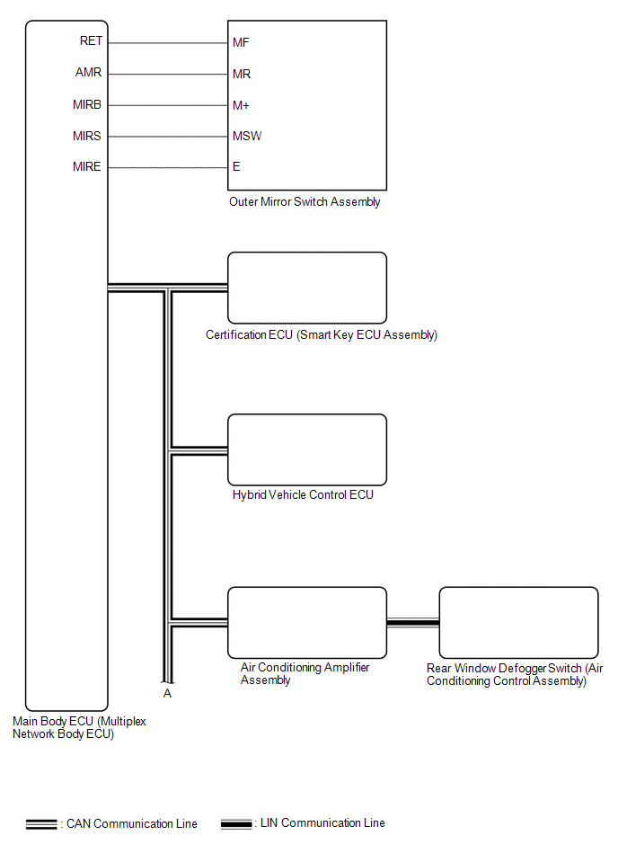
 Communication Table
 | Sender | Receiver | Signal | Line |
|---|---|---|---|
| Main Body ECU (Multiplex Network Body ECU) | Outer Mirror Control ECU Assembly |
| CAN |
| Outer Mirror Control ECU Assembly | Main Body ECU (Multiplex Network Body ECU) |
| CAN |
| Certification ECU (Smart Key ECU Assembly) | Main Body ECU (Multiplex Network Body ECU) | Key ID signal | CAN |
| Air Conditioning Amplifier Assembly | Outer Mirror Control ECU Assembly | Mirror heater drive request signal | CAN |
| Hybrid Vehicle Control ECU | Main Body ECU (Multiplex Network Body ECU) | Reverse signal | CAN |
| Rear Window Defogger switch (Air Conditioning Control Assembly) | Air Conditioning Amplifier Assembly | Mirror heater switch (rear window defogger switch) operation signal | LIN |
READ NEXT:
 System Description
SYSTEM DESCRIPTION POWER MIRROR CONTROL SYSTEM (w/ Memory) DESCRIPTION (a) This system has the following functions: electrical remote control mirror function, memory and reactivation function, power r
How To Proceed With Troubleshooting
CAUTION / NOTICE / HINT HINT:
Use the following procedure to troubleshoot the power mirror control system (w/ Memory).
*: Use the Techstream.
PROCEDURE 1. VEHICLE BROUGHT TO WORKSHOP
Operation Check
OPERATION CHECK CHECK ELECTRICAL REMOTE CONTROL MIRROR FUNCTION (a) Turn the power switch on (IG). (b) b. With the mirror select switch driver side switch on, check that the outer rear view mirror ass
SEE MORE:
Main Microcomputer in Front Radar Sensor Calibration/Parameter Memory Failure (C1A8C46,C1A8D1C,C1A9000,C1A9100)
DESCRIPTION When an internal malfunction is detected in the millimeter wave radar sensor assembly, a DTC is stored. DTC No. Detection Item DTC Detection Condition Trouble Area C1A8C46 Main Microcomputer in Front Radar Sensor Calibration/Parameter Memory Failure When the engine switc
Installation
INSTALLATION PROCEDURE 1. INSTALL TRANSMISSION FLOOR SHIFT ASSEMBLY (a) Engage the clamp to connect the wire harness to the transmission floor shift assembly. (b) Connect the shift lock control ECU connector. (c) Engage the clamp to connect the wire harness to the transmission floor shift assembly.
© 2016-2026 Copyright www.lexguide.net
