Lexus ES: Parts Location
Lexus ES (XZ10) Service Manual / Engine & Hybrid System / A25a-fks (fuel) / Fuel System / Parts Location
PARTS LOCATION
ILLUSTRATION
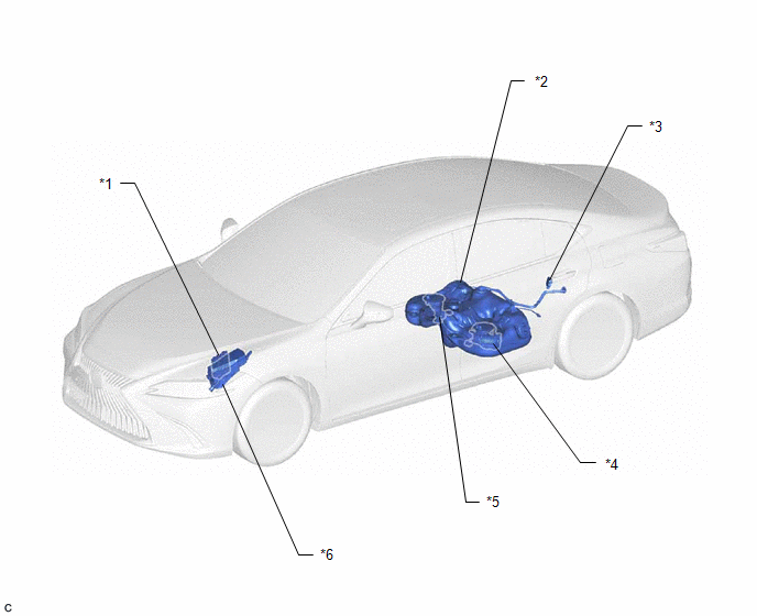
| *1 | ECM | *2 | FUEL TANK ASSEMBLY |
| *3 | FUEL PUMP CONTROL ECU | *4 | FUEL SUCTION TUBE WITH PUMP AND GAUGE ASSEMBLY - FUEL PUMP (for Low Pressure) - FUEL MAIN VALVE ASSEMBLY - FUEL SENDER GAUGE ASSEMBLY |
| *5 | FUEL TANK VENT TUBE ASSEMBLY - NO. 2 FUEL SENDER GAUGE ASSEMBLY | *6 | NO. 1 ENGINE ROOM RELAY BLOCK ASSEMBLY AND NO. 1 ENGINE ROOM JUNCTION BLOCK ASSEMBLY - EFI-MAIN NO. 1 RELAY - EFI-MAIN NO. 2 RELAY - IG2 NO. 1 RELAY - EFI-MAIN NO. 2 FUSE - INJ FUSE |
ILLUSTRATION
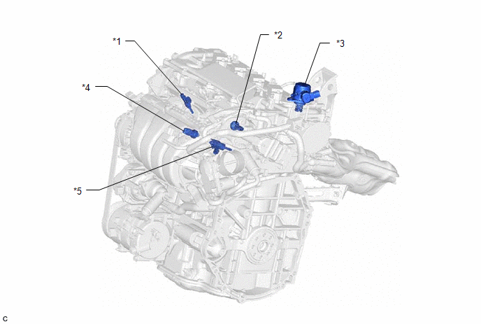
| *1 | PORT FUEL INJECTOR ASSEMBLY | *2 | NO. 2 FUEL PRESSURE SENSOR (for Low Pressure) |
| *3 | FUEL PUMP ASSEMBLY (for High Pressure) | *4 | FUEL PRESSURE SENSOR (for High Pressure) |
| *5 | DIRECT FUEL INJECTOR ASSEMBLY | - | - |
READ NEXT:
 System Diagram
SYSTEM DIAGRAM HIGH PRESSURE SIDE FUEL SYSTEM WIRING DIAGRAM LOW PRESSURE SIDE FUEL SYSTEM WIRING DIAGRAM
On-vehicle Inspection
ON-VEHICLE INSPECTION PROCEDURE 1. CHECK FUEL PUMP OPERATION AND INSPECT FOR FUEL LEAK (a) Check fuel pump operation. (1) Connect the Techstream to the DLC3. (2) Turn the engine switch on (IG). NOTICE
SEE MORE:
Front Passenger Side Power Window Auto Up / Down Function does not Operate with Front Passenger Side Power Window Switch
DESCRIPTION If the manual up and down functions operate normally but the auto up and down functions do not, the power window control system may be in fail-safe mode. If power window initialization has not been performed, the auto up and down functions will not operate. Click here WIRING DIAGRAM C
Components
COMPONENTS ILLUSTRATION *1 REAR HEIGHT CONTROL SENSOR SUB-ASSEMBLY LH - - N*m (kgf*cm, ft.*lbf): Specified torque - -
© 2016-2026 Copyright www.lexguide.net
