Lexus ES: Operation Check
OPERATION CHECK
CHECK ELECTRICAL REMOTE CONTROL MIRROR FUNCTION
(a) Turn the power switch on (IG).
(b) b. With the mirror select switch driver side switch on, check that the outer rear view mirror assembly (driver door) surface moves up, down, left and right normally
(c) With the mirror select switch front passenger side switch on, check that the outer rear view mirror assembly (front passenger door) surface moves up, down, left and right normally.
CHECK MEMORY AND REACTIVATION FUNCTION
HINT:
The SET, M1, M2 and M3 seat memory switches are shown in the illustration.
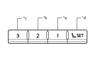
| *a | M1 Switch |
| *b | M2 Switch |
| *c | M3 Switch |
| *d | SET Switch |
(a) Turn the power switch on (IG) and move the shift lever to P.
(b) Check the M1 switch.
.png)
| *a | Turn to Fully Left Position |
(1) Using the outer mirror switch assembly, turn the mirror surface to the fully left position.
(2) Check that the buzzer sounds for 0.5 seconds and the seat and mirror surface position is memorized when the M1 switch is pressed within 3 seconds of the SET switch being pressed.
NOTICE:
- The mirror surface position will also be memorized when the M1 switch is pressed after first pressing and holding the SET switch.
- The mirror surface position will not be memorized when the SET switch and M1 switch are pressed simultaneously.
- The mirror surface position will not be memorized when 2 or more of the memory switches are pressed simultaneously (for example, M1 and M2) after first pressing the SET switch.
(3) Using the outer mirror switch assembly, turn the mirror surface to the fully right position.
(4) Press the M1 switch.
(5) Check that the buzzer sounds for 0.1 seconds and the mirror surface automatically moves to the memorized fully left position.
.png)
| *a | Turn to Fully Right Position |
(c) Check the M2 switch.
(1) Using the outer mirror switch assembly, turn the mirror surface to the fully right position.
(2) Check that the buzzer sounds for 0.5 seconds and the seat and mirror surface position is memorized when the M2 switch is pressed within 3 seconds of the SET switch being pressed.
NOTICE:
- The mirror surface position will also be memorized when the M2 switch is pressed after first pressing and holding the SET switch.
- The mirror surface position will not be memorized when the SET switch and M2 switch are pressed simultaneously.
- The mirror surface position will not be memorized when 2 or more of the memory switches are pressed simultaneously (for example, M1 and M2) after first pressing the SET switch.
(3) Using the outer mirror switch assembly, turn the mirror surface to the fully left position.
(4) Press the M2 switch.
(5) Check that the buzzer sounds for 0.1 seconds and the mirror surface automatically moves to the memorized fully right position.
(d) Check the M3 switch.
| *a | Turn to Fully Left Position |
(1) Using the outer mirror switch assembly, turn the mirror surface to the fully left position.
(2) Check that the buzzer sounds for 0.5 seconds and the seat and mirror surface position is memorized when the M1 switch is pressed within 3 seconds of the SET switch being pressed.
NOTICE:
- The mirror surface position will also be memorized when the M3 switch is pressed after first pressing and holding the SET switch.
- The mirror surface position will not be memorized when the SET switch and M3 switch are pressed simultaneously.
- The mirror surface position will not be memorized when 2 or more of the memory switches are pressed simultaneously (for example, M1 and M2) after first pressing the SET switch.
(3) Using the outer mirror switch assembly, turn the mirror surface to the fully right position.
(4) Press the M3 switch.
(5) Check that the buzzer sounds for 0.1 seconds and the mirror surface automatically moves to the memorized fully left position.
CHECK POWER RETRACT MIRROR FUNCTION
(a) Turn the power switch on (IG).
(b) At each outer rear view mirror assembly position, check the retractable mirror operation when operating the retractable outer mirror switch.
(1) Move both outer rear view mirror assemblies to the driving position.
.png)
(2) Press the retractable outer mirror switch.
(3) Check that the right and left outer rear view mirror assemblies move from the driving position to the retract position.
(4) Move both outer rear view mirror assemblies to the driving position.
.png)
(5) Move one of the outer rear view mirror assemblies to the forward position by hand.
(6) Press the retractable outer mirror switch.
(7) Check that the outer rear view mirror assembly in the forward position moves to the retract position, and check that the other mirror moves to the retract position.
(8) Move the outer rear view mirror assemblies to the driving position.
.png)
(9) Move one of the outer rear view mirror assemblies to the retract position by hand.
(10) Press the retractable outer mirror switch.
(11) Check that the outer rear view mirror assembly in the driving position moves to the retract position.
(12) Move both outer rear view mirror assemblies to the retract position.
.png)
(13) Press the retractable outer mirror switch.
(14) Check that both outer rear view mirror assemblies move from the retract position to the driving position.
(15) Move both outer rear view mirror assemblies to the retract position.
.png)
(16) Move one of the outer rear view mirror assemblies to the driving position by hand.
(17) Press the retractable outer mirror switch.
(18) Check that the retracted outer rear view mirror assembly moves to the driving position.
(c) Check the operation of the outer rear view mirror assemblies according to retractable outer mirror switch operations and power switch condition.
(1) When the outer rear view mirror assemblies are operating, turn the power switch off and check that the mirror operation stops immediately.
(2) Turn the power switch on (ACC) and press the retractable outer mirror switch. Check that the outer rear view mirror assemblies operate in the opposite direction.
(d) Check the operation of the outer rear view mirror assembly when it is blocked by an obstacle.
(1) When an outer rear view mirror assembly is moving to the retracted or driving position, block it by hand. Check that stops moving.
(2) With the outer rear view mirror assembly stopped partway, push the retractable outer mirror switch. Check that the outer rear view mirror assembly moves in the opposite direction.
CHECK AUTO POWER RETRACT MIRROR FUNCTION
HINT:
The default setting is Door Lock. If necessary, the function can be set to "ACC" through the customize function.
Click here .gif)
(a) With the power switch off and the retractable outer mirror switch in auto position, when the doors are unlocked through the entry function, wireless function or key-linked function, check that both outer rear view mirror assemblies move from the retract position to the driving position, and stop in the driving position.
(b) With the power switch off and the retractable outer mirror switch in auto position, when the doors are locked through the entry function, wireless function or key-linked function, check that both outer rear view mirror assemblies move from the driving position to the retract position, and stop in the retract position.
(c) When the power switch is on (ACC) and then turned off while the retractable outer mirror switch is in auto position, check that both outer rear view mirror assemblies automatically move from the driving position to the retract position.
(d) When the power switch is off and then turned on (ACC) while the retractable outer mirror switch is in auto position, check that both outer rear view mirror assemblies automatically move from the retract position to the driving position.
CHECK REVERSE SHIFT-LINKED FUNCTION
(a) Turn the power switch on (IG).
(b) Turn the mirror select switch L or R switch on.
(c) Check that the mirror surface turns downward when the shift lever is moved to R.
(d) Check that the mirror surface position returns to the original position when one of the following conditions is met:
- Shift lever is moved to any position other than R.
- Both mirror select switch L and R switches are off.
- power switch is turned off.
CHECK REVERSE SHIFT-LINKED MIRROR POSITION MEMORIZATION FUNCTION
HINT:
The reverse shift-linked mirror position memorization function can be customized.
(a) Turn the power switch on (IG).
(b) Turn the mirror select switch L or R switch on.
(c) Check that the mirror surface turns downward when the shift lever is moved to R.
(d) While the mirror is in the reverse shift-linked operation position, move the mirror surface to the desired position.
HINT:
If the mirror surface is set to turn to the upward position, the mirror surface turns upward when the shift lever is moved to R.
(e) Check that the mirror surface moves to its normal position when the shift lever is moved to a position other than R, and then moves back to the memorized position when the shift lever is moved to R again.
CHECK MEMORY CALL FUNCTION
(a) Memory call function check
(1) With an electrical key transmitter sub-assembly recognition code registered, perform a wireless door unlock operation and check that opening the driver door causes the following:
- The buzzer sounds for 0.1 seconds.
- The driver seat and mirror surface positions automatically move to the memorized positions.
HINT:
- The registered electrical key transmitter sub-assembly recognition code is recalled automatically.
- If the memory call function is not operated, the buzzer will not sound.
(b) With the power switch on (IG) and the driver door closed, press and hold the M1, M2 or M3 switch while carrying the electrical key transmitter sub-assembly. The main body ECU (multiplex network body ECU) will enter electrical key transmitter sub-assembly recognition code registration mode to allow a key to be linked to mirror surface memory position.
HINT:
If the seat memory switch is released before entering registration mode, the main body ECU (multiplex network body ECU) will not enter registration mode.
(c) When the manual door lock switch is pressed, check that the buzzer sounds once (0.5 seconds).
(d) With the power switch on (IG) and the driver door closed, press and hold the SET switch while carrying the electrical key transmitter sub-assembly. The main body ECU (multiplex network body ECU) will enter electrical key transmitter sub-assembly recognition code deletion mode.
HINT:
If the seat memory switch is released before entering deletion mode, the main body ECU (multiplex network body ECU) will not enter deletion mode.
(e) When the manual door lock switch is pressed, check that the buzzer sounds twice (0.1 seconds each time).
CHECK MEMORY CALL EMERGENCY STOP FUNCTION
(a) While a memory call function is operating, check that any one of the following actions will stop the memory call operation: 1) pressing the SET, M1, M2 or M3 switch, 2) moving the shift lever to R, 3) moving the mirror surface manually, or 4) moving the mirror surface to the uppermost, lowermost, leftmost or rightmost position.
CHECK MIRROR HEATER FUNCTION
(a) Turn the power switch on (IG).
(b) Check that pressing the mirror heater switch (rear window defogger switch) illuminates the indicator and warms the mirror surfaces.
(c) Check that after approximately 15 minutes, the indicator light turns off and the mirror heaters deactivate.
CHECK AUTOMATIC GLARE-RESISTANT EC MIRROR FUNCTION
(a) Check that the automatic glare-resistant EC mirror function of the outer rear view mirror assemblies operates when the automatic glare-resistant function of the inner rear view mirror assembly operates.
READ NEXT:
 Customize Parameters
CUSTOMIZE PARAMETERS CUSTOMIZE POWER MIRROR CONTROL SYSTEM (w/ Memory) NOTICE:
When the customer requests a change in a function, first make sure that the function can be customized.
Record the c
Problem Symptoms Table
PROBLEM SYMPTOMS TABLE HINT:
Use the table below to help determine the cause of problem symptoms. If multiple suspected areas are listed, the potential causes of the symptoms are listed in order of
Terminals Of Ecu
TERMINALS OF ECU CHECK OUTER MIRROR CONTROL ECU ASSEMBLY (DRIVER DOOR) (a) Disconnect the J28 outer mirror control ECU assembly (driver door) connector. (b) Measure the voltage and resistance accordi
SEE MORE:
Components
COMPONENTS ILLUSTRATION *A w/o AVS - - *1 FRONT SHOCK ABSORBER WITH COIL SPRING *2 FRONT SPEED SENSOR *3 FRONT STABILIZER LINK ASSEMBLY *4 FRONT FLEXIBLE HOSE *5 STEERING KNUCKLE *6 FRONT SHOCK ABSORBER LOCK NUT CAP Tightening torque for "Major areas in
Torque Converter Clutch Actuator Stuck On (P07407E)
DESCRIPTION The ECM uses signals from the throttle position sensor, mass air flow meter, transmission revolution sensor (NT), transmission revolution sensor (NC) and crankshaft position sensor to help determine the engagement timing of the lock-up clutch. The ECM monitors the engagement of the clutc
