Lexus ES: System Diagram
SYSTEM DIAGRAM
(a) The CAN communication system is composed of 5 buses.
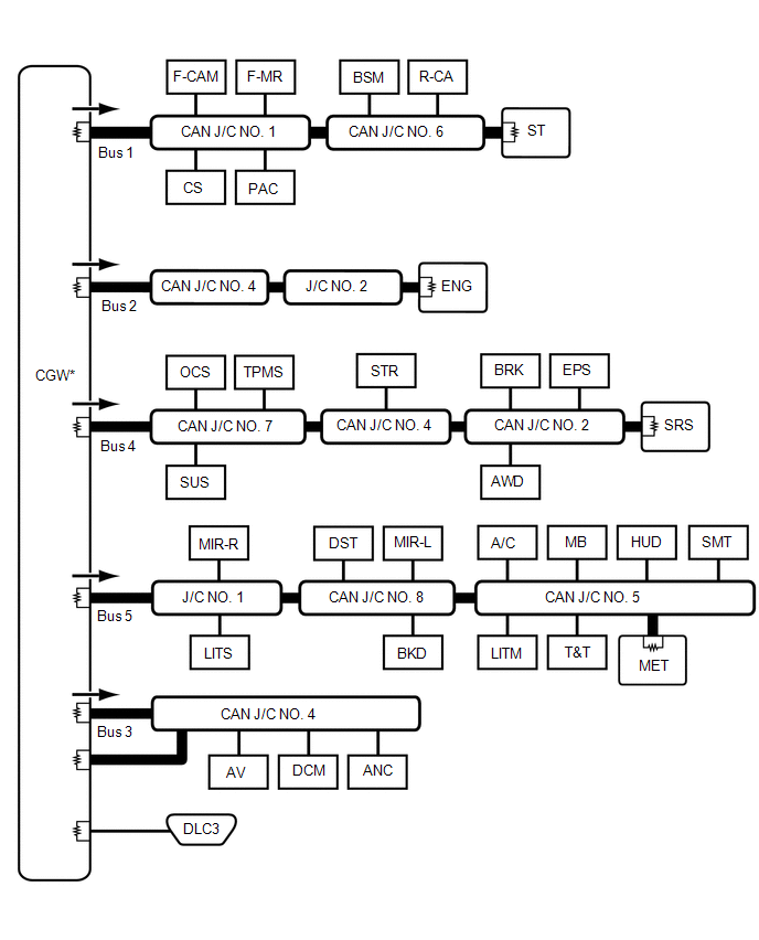
.png) | CAN Main Bus Line | .png) | Terminating Resistor |
.png) | CAN Branch Line | * | Gateway Function Equipped ECU |
.png) | Bus Monitoring Direction | - | - |
| Connected to | Code | ECU/Sensor Name | CAN DTC Storage | Note |
|---|---|---|---|---|
| - | CGW | Central Gateway ECU (Network Gateway ECU) | - | - |
| - | DLC3 | DLC3 | - | - |
| Bus 1 | F-CAM | Forward Recognition Camera | Available | - |
| F-MR | Millimeter Wave Radar Sensor Assembly | Available | - | |
| BSM | Blind Spot Monitor Sensor RH | Available | w/ Blind Spot Monitor System | |
| R-CA | Rear Television Camera Assembly | Available | - | |
| CS | Clearance Warning ECU Assembly | Available | w/ Parking Support Brake System | |
| PAC | Parking Assist ECU | Available | w/ Panoramic View Monitor System | |
| CAN J/C NO. 1 | No. 1 CAN Junction Connector | - | - | |
| CAN J/C NO. 6 | No. 6 CAN Junction Connector | - | - | |
| ST | No. 1 CAN Junction Terminal | - | - | |
| Bus 2 | ENG | ECM | Available | - |
| J/C NO. 2 | No. 2 Junction Connector | - | - | |
| CAN J/C NO. 4 | No. 4 CAN Junction Connector | - | - | |
| Bus 3 | AV | Radio Receiver Assembly | Available | - |
| DCM | DCM (Telematics Transceiver) | Available | w/ Telematics Transceiver | |
| ANC | Stereo Component Equalizer Assembly | Available | w/ Active Noise Control System | |
| CAN J/C NO. 4 | No. 4 CAN Junction Connector | - | - | |
| Bus 4 | TPMS | Tire Pressure Warning ECU and Receiver | Available | - |
| OCS | Occupant Detection ECU | Available | - | |
| SUS | Absorber Control ECU | Available | w/ AVS System | |
| BRK | Brake Actuator Assembly | Available | - | |
| EPS | Rack and Pinion Power Steering Gear Assembly | Available | - | |
| STR | Steering Sensor | - | - | |
| AWD | 4WD ECU Assembly | Available | for AWD | |
| SRS | Airbag ECU Assembly | Available | - | |
| CAN J/C NO. 2 | No. 2 CAN Junction Connector | - | - | |
| CAN J/C NO. 4 | No. 4 CAN Junction Connector | - | - | |
| CAN J/C NO. 7 | No. 7 CAN Junction Connector | - | - | |
| Bus 5 | LITS | Headlight ECU Sub-assembly RH | Available | - |
| MIR-R | Outer Mirror Control ECU Assembly RH | Available | w/ Seat Position Memory System | |
| DST | Position Control ECU Assembly LH | - | w/ Seat Position Memory System | |
| MIR-L | Outer Mirror Control ECU Assembly LH | Available | w/ Seat Position Memory System | |
| A/C | Air Conditioning Amplifier Assembly | Available | - | |
| MB | Main Body ECU (Multiplex Network Body ECU) | Available | Connected to LIN communication system | |
| HUD | Meter Mirror Sub-assembly | Available | w/ Headup Display System | |
| SMT | Certification ECU (Smart Key ECU Assembly) | Available | - | |
| LITM | Headlight ECU Sub-assembly LH | Available | - | |
| T&T | Multiplex Tilt and Telescopic ECU | Available | w/ Power Tilt and Power Telescopic System | |
| MET | Combination Meter Assembly | Available | - | |
| BKD | Luggage Closer Motor Assembly | Available | w/ Power Trunk Lid System | |
| CAN J/C NO. 5 | No. 5 CAN Junction Connector | - | - | |
| CAN J/C NO. 8 | No. 8 CAN Junction Connector | - | - | |
| J/C NO. 1 | No. 1 Junction Connector | - | - |
READ NEXT:
 System Diagram
SYSTEM DIAGRAM (a) The CAN communication system is composed of 5 buses. CAN Main Bus Line Terminating Resistor CAN Branch Line * Gateway Function Equipped ECU Bus Monitor
Parts Location
PARTS LOCATION ILLUSTRATION *1 HEADLIGHT ECU SUB-ASSEMBLY RH *2 BRAKE ACTUATOR ASSEMBLY *3 FORWARD RECOGNITION CAMERA *4 ECM *5 RACK AND PINION POWER STEERING GEAR ASSEMBLY
Parts Location
PARTS LOCATION ILLUSTRATION *1 HEADLIGHT ECU SUB-ASSEMBLY RH *2 BRAKE ACTUATOR ASSEMBLY *3 FORWARD RECOGNITION CAMERA *4 ECM *5 RACK AND PINION POWER STEERING GEAR ASSEMBLY
SEE MORE:
System Diagram
SYSTEM DIAGRAM HEADLIGHT ASSEMBLY CIRCUIT (for LED Type Turn Signal Light) HEADLIGHT ASSEMBLY CIRCUIT (for Bulb Type Turn Signal Light) (for TMC Made) HEADLIGHT ASSEMBLY CIRCUIT (for Bulb Type Turn Signal Light) (for TMMK Made)
Drive Motor "A" Performance (P0A9000)
DTC SUMMARY MALFUNCTION DESCRIPTION This DTC indicates that magnetic force deterioration of the permanent magnet located in the rotor inside the motor (MG2) has been detected. The cause of this malfunction may be one of the following: Area Main Malfunction Description Inverter Inverter wi
