Lexus ES: Parts Location
PARTS LOCATION
ILLUSTRATION
.png)
| *1 | HEADLIGHT ECU SUB-ASSEMBLY RH | *2 | BRAKE ACTUATOR ASSEMBLY |
| *3 | FORWARD RECOGNITION CAMERA | *4 | ECM |
| *5 | RACK AND PINION POWER STEERING GEAR ASSEMBLY | *6 | HEADLIGHT ECU SUB-ASSEMBLY LH |
| *7 | MILLIMETER WAVE RADAR SENSOR ASSEMBLY | *8 | BLIND SPOT MONITOR SENSOR RH (w/ Blind Spot Monitor System) |
| *9 | TIRE PRESSURE WARNING ECU AND RECEIVER | *10 | OUTER MIRROR CONTROL ECU ASSEMBLY RH (w/ Seat Position Memory System) |
| *11 | REAR TELEVISION CAMERA ASSEMBLY | *12 | ABSORBER CONTROL ECU (w/ AVS System) |
| *13 | OUTER MIRROR CONTROL ECU ASSEMBLY LH (w/ Seat Position Memory System) | *14 | LUGGAGE CLOSER MOTOR ASSEMBLY (w/ Power Trunk Lid System) |
| *15 | NO. 6 CAN JUNCTION CONNECTOR | *16 | NO. 7 CAN JUNCTION CONNECTOR |
| *17 | NO. 8 CAN JUNCTION CONNECTOR | *18 | NO. 1 CAN JUNCTION TERMINAL |
ILLUSTRATION
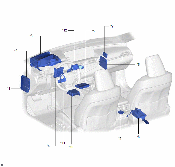
| *1 | INSTRUMENT PANEL JUNCTION BLOCK ASSEMBLY | *2 | MAIN BODY ECU (MULTIPLEX NETWORK BODY ECU) |
| *3 | METER MIRROR SUB-ASSEMBLY (w/ Headup Display System) | *4 | AIR CONDITIONING AMPLIFIER ASSEMBLY |
| *5 | DCM (TELEMATICS TRANSCEIVER) (w/ Telematics Transceiver) | *6 | CERTIFICATION ECU (SMART KEY ECU ASSEMBLY) |
| *7 | CENTRAL GATEWAY ECU (NETWORK GATEWAY ECU) | *8 | PARKING ASSIST ECU (w/ Panoramic View Monitor System) |
| *9 | OCCUPANT DETECTION ECU | *10 | AIRBAG ECU ASSEMBLY |
| *11 | STEERING SENSOR | *12 | STEREO COMPONENT EQUALIZER ASSEMBLY (w/ Active Noise Control System) |
ILLUSTRATION
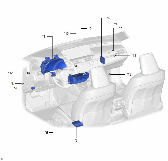
| *1 | COMBINATION METER ASSEMBLY | *2 | RADIO RECEIVER ASSEMBLY |
| *3 | POSITION CONTROL ECU ASSEMBLY LH (w/ Seat Position Memory System) | *4 | DLC3 |
| *5 | MULTIPLEX TILT AND TELESCOPIC ECU (w/ Power Tilt and Power Telescopic System) | *6 | CLEARANCE WARNING ECU ASSEMBLY (w/ Parking Support Brake System) |
| *7 | NO. 1 CAN JUNCTION CONNECTOR | *8 | NO. 2 CAN JUNCTION CONNECTOR |
| *9 | NO. 4 CAN JUNCTION CONNECTOR | *10 | NO. 5 CAN JUNCTION CONNECTOR |
| *11 | NO. 1 JUNCTION CONNECTOR | *12 | NO. 2 JUNCTION CONNECTOR |
| *13 | OPTION CONNECTOR (BUS BUFFER ECU) (w/ CAN Compatible Optional Devices) | - | - |
READ NEXT:
 Precaution
PRECAUTION NOTICE FOR INITIALIZATION NOTICE: When disconnecting the cable from the negative (-) battery terminal, initialize the following systems after the cable is reconnected. System See Proce
SEE MORE:
Removal
REMOVAL CAUTION / NOTICE / HINT The necessary procedures (adjustment, calibration, initialization or registration) that must be performed after parts are removed and installed, or replaced during windshield glass sub-assembly removal/installation are shown below. Necessary Procedure After Parts Remo
On-vehicle Inspection
ON-VEHICLE INSPECTION PROCEDURE 1. INSPECT BRAKE FLUID LEVEL IN RESERVOIR (a) Check the fluid level. Brake Fluid: SAE J1703 or FMVSS No. 116 DOT3 SAE J1704 or FMVSS No. 116 DOT4 NOTICE: If using a dropper to adjust the fluid amount, make sure that the dropper has not been used with mineral oils,
