Lexus ES: Parts Location
PARTS LOCATION
ILLUSTRATION
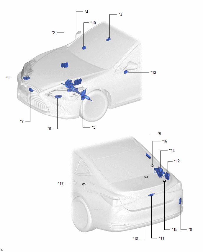
| *1 | HEADLIGHT ECU SUB-ASSEMBLY RH | *2 | BRAKE ACTUATOR ASSEMBLY |
| *3 | FORWARD RECOGNITION CAMERA | *4 | ECM |
| *5 | RACK AND PINION POWER STEERING GEAR ASSEMBLY | *6 | HEADLIGHT ECU SUB-ASSEMBLY LH |
| *7 | MILLIMETER WAVE RADAR SENSOR ASSEMBLY | *8 | BLIND SPOT MONITOR SENSOR RH (w/ Blind Spot Monitor System) |
| *9 | TIRE PRESSURE WARNING ECU AND RECEIVER | *10 | OUTER MIRROR CONTROL ECU ASSEMBLY RH (w/ Seat Position Memory System) |
| *11 | REAR TELEVISION CAMERA ASSEMBLY | *12 | ABSORBER CONTROL ECU (w/ AVS System) |
| *13 | OUTER MIRROR CONTROL ECU ASSEMBLY LH (w/ Seat Position Memory System) | *14 | LUGGAGE CLOSER MOTOR ASSEMBLY (w/ Power Trunk Lid System) |
| *15 | NO. 6 CAN JUNCTION CONNECTOR | *16 | NO. 7 CAN JUNCTION CONNECTOR |
| *17 | NO. 8 CAN JUNCTION CONNECTOR | *18 | NO. 1 CAN JUNCTION TERMINAL |
ILLUSTRATION
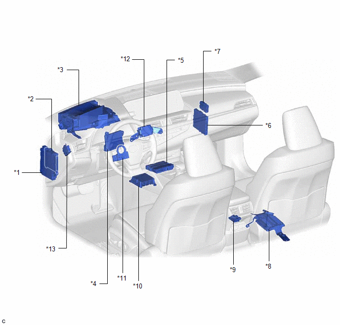
| *1 | INSTRUMENT PANEL JUNCTION BLOCK ASSEMBLY | *2 | MAIN BODY ECU (MULTIPLEX NETWORK BODY ECU) |
| *3 | METER MIRROR SUB-ASSEMBLY (w/ Headup Display System) | *4 | AIR CONDITIONING AMPLIFIER ASSEMBLY |
| *5 | DCM (TELEMATICS TRANSCEIVER) (w/ Telematics Transceiver) | *6 | CERTIFICATION ECU (SMART KEY ECU ASSEMBLY) |
| *7 | CENTRAL GATEWAY ECU (NETWORK GATEWAY ECU) | *8 | PARKING ASSIST ECU (w/ Panoramic View Monitor System) |
| *9 | OCCUPANT DETECTION ECU | *10 | AIRBAG ECU ASSEMBLY |
| *11 | STEERING SENSOR | *12 | STEREO COMPONENT EQUALIZER ASSEMBLY (w/ Active Noise Control System) |
| *13 | 4WD ECU ASSEMBLY (for AWD) | - | - |
ILLUSTRATION
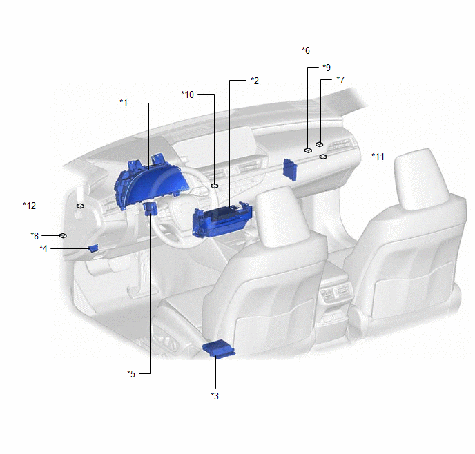
| *1 | COMBINATION METER ASSEMBLY | *2 | RADIO RECEIVER ASSEMBLY |
| *3 | POSITION CONTROL ECU ASSEMBLY LH (w/ Seat Position Memory System) | *4 | DLC3 |
| *5 | MULTIPLEX TILT AND TELESCOPIC ECU (w/ Power Tilt and Power Telescopic System) | *6 | CLEARANCE WARNING ECU ASSEMBLY (w/ Parking Support Brake System) |
| *7 | NO. 1 CAN JUNCTION CONNECTOR | *8 | NO. 2 CAN JUNCTION CONNECTOR |
| *9 | NO. 4 CAN JUNCTION CONNECTOR | *10 | NO. 5 CAN JUNCTION CONNECTOR |
| *11 | NO. 1 JUNCTION CONNECTOR | *12 | NO. 2 JUNCTION CONNECTOR |
READ NEXT:
 Parts Location
PARTS LOCATION ILLUSTRATION *1 HEADLIGHT ECU SUB-ASSEMBLY RH *2 BRAKE ACTUATOR ASSEMBLY *3 FORWARD RECOGNITION CAMERA *4 ECM *5 RACK AND PINION POWER STEERING GEAR ASSEMBLY
Precaution
PRECAUTION NOTICE FOR INITIALIZATION NOTICE: When disconnecting the cable from the negative (-) battery terminal, initialize the following systems after the cable is reconnected. System See Proce
SEE MORE:
ECM Power Source Circuit
DESCRIPTION When the engine switch is turned on (IG), the battery voltage is applied to the IGSW terminal of the ECM. The output signal from the MREL terminal of the ECM causes a current to flow to the coil of the EFI-MAIN NO. 1 relay, closing the contacts and supplying power to terminals +B and +B2
Fuel Lid Opener does not Operate
DESCRIPTION When the trunk and fuel switch assembly (fuel lid opener switch) is pushed, a trunk and fuel switch assembly (fuel lid opener switch) signal is sent to the ECM. The ECM turns on the FUEL OPN relay and EFI-MAIN NO. 1 relay, and the fuel lid lock with motor assembly opens the fuel lid. Whe
