Lexus ES: Power Window Master Switch
Components
COMPONENTS
ILLUSTRATION
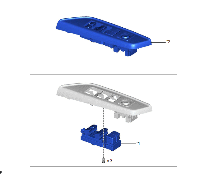
| *1 | MULTIPLEX NETWORK MASTER SWITCH ASSEMBLY | *2 | MULTIPLEX NETWORK MASTER SWITCH ASSEMBLY WITH FRONT DOOR UPPER ARMREST BASE PANEL |
Removal
REMOVAL
PROCEDURE
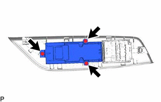
1. REMOVE MULTIPLEX NETWORK MASTER SWITCH ASSEMBLY WITH FRONT DOOR UPPER ARMREST BASE PANEL
Click here .gif)
2. REMOVE MULTIPLEX NETWORK MASTER SWITCH ASSEMBLY
| (a) Remove the 3 screws and multiplex network master switch assembly. |
|
Inspection
INSPECTION
PROCEDURE
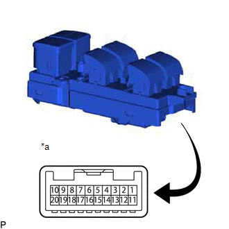
1. INSPECT MULTIPLEX NETWORK MASTER SWITCH ASSEMBLY
| (a) Check that the LEDs illuminate. (1) Apply auxiliary battery voltage to the multiplex network master switch assembly and check that the LEDs illuminate. OK:
If the result is not as specified, replace the multiplex network master switch assembly. |
|
READ NEXT:
 Components
COMPONENTS ILLUSTRATION *A for Driver Side *B for Front Passenger Side *1 COURTESY LIGHT ASSEMBLY *2 FRONT DOOR TRIM BOARD SUB-ASSEMBLY *3 MULTIPLEX NETWORK MASTER SWITCH ASS
Removal
REMOVAL CAUTION / NOTICE / HINT The necessary procedures (adjustment, calibration, initialization, or registration) that must be performed after parts are removed and installed, or replaced during pow
SEE MORE:
Disassembly
DISASSEMBLY PROCEDURE 1. REMOVE END COVER (a) Using a T30 "TORX" socket wrench, remove the 5 screws and end cover. NOTICE:
Hold the pump so that the pump installation surface, fitting parts and oil pipe will not be damaged.
As the housing deforms when force is applied, do not secure the ho
Open in Bus 3 Main Bus Line
DESCRIPTION There may be an open circuit in one of the CAN main bus lines when the resistance between terminals 6 (CA3H) and 21 (CA3L) of the central gateway ECU (network gateway ECU) is 70 Ω or higher. Symptom Trouble Area Resistance between terminals 6 (CA3H) and 21 (CA3L) of the central
