Lexus ES: System Diagram
SYSTEM DIAGRAM
READ NEXT:
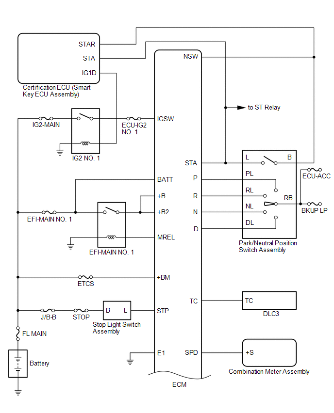
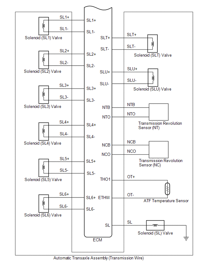
 System Diagram
SYSTEM DIAGRAM
Terminals Of Ecm
TERMINALS OF ECM ECM HINT: The standard voltage and resistance of each ECM terminal is shown in the table below. In the table, first follow the information under "Condition". Look under "Terminal No.
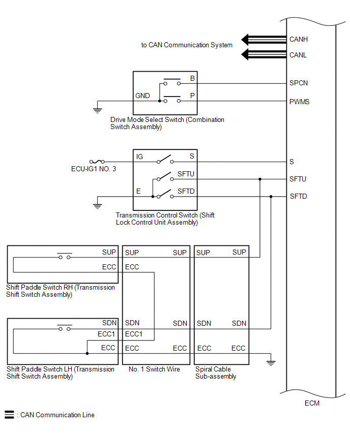
Transmission Control Switch Circuit
DESCRIPTION When the shift lever is in S and moved toward "-" or "+", it is possible to select different shift ranges (S1 to S8). Moving the shift lever toward "+" increases the shift range by one, an
SEE MORE:
Brake Actuator Operation Sound is Loud during Initial Check
CAUTION / NOTICE / HINT NOTICE: After replacing the skid control ECU (brake actuator assembly), perform acceleration sensor zero point calibration and store system information memorization. Click here PROCEDURE 1. PERFORM ROAD TEST (a) After turning the engine switch on (IG), compare the
Inspection
INSPECTION PROCEDURE 1. INSPECT DIRECT FUEL INJECTOR ASSEMBLY NOTICE: This inspection is for checking the direct fuel injector assembly for an open or short. Because the direct fuel injector assembly of this vehicle is a high-pressure type, fuel injection volume cannot be checked. (a) Measure the
© 2016-2026 Copyright www.lexguide.net
