Lexus ES: Terminals Of Ecm
TERMINALS OF ECM
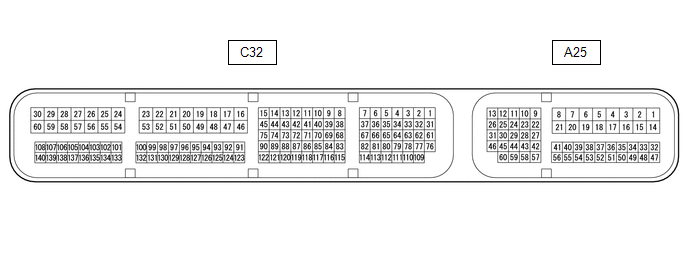
ECM
HINT:
The standard voltage and resistance of each ECM terminal is shown in the table below.
In the table, first follow the information under "Condition". Look under "Terminal No. (Symbol)" for the terminals to be inspected. The standard voltage or resistance between the terminals is shown under "Specified Condition".
Use the illustration above as a reference for the ECM terminals.
| Terminal No. (Symbol) | Wiring Color | Terminal Description | Condition | Specified Condition |
|---|---|---|---|---|
| A25-1 (BATT) - C32-53 (E1) | R - W-B | Battery (for measuring battery voltage and for ECM memory) | Always | 11 to 14 V |
| A25-2 (+B) - C32-53 (E1) | L - W-B | Power source of ECM | Engine switch on (IG) | 11 to 14 V |
| A25-3 (+B2) - C32-53 (E1) | L - W-B | Power source of ECM | Engine switch on (IG) | 11 to 14 V |
| A25-8 (+BM) - C32-53 (E1) | G - W-B | Power source of ECM | Always | 11 to 14 V |
| A25-13 (CANH) - C32-53 (E1) | B - W-B | CAN communication line | Engine switch on (IG) | Pulse generation |
| A25-17 (S) - C32-53 (E1) | GR - W-B | S shift position switch signal | Engine switch on (IG) and shift lever in S | 11 to 14 V |
| Engine switch on (IG) and shift lever not in S | Below 1 V | |||
| A25-26 (CANL) - C32-53 (E1) | W - W-B | CAN communication line | Engine switch on (IG) | Pulse generation |
| A25-27 (STP) - C32-53 (E1) | SB - W-B | Stop light switch signal | Brake pedal depressed | 7.5 to 14 V |
| Brake pedal released | Below 1 V | |||
| A25-37 (SFTD) - C32-53 (E1) | W - W-B | Down-shift switch signal | Engine switch on (IG) | 11 to 14 V |
| Engine switch on (IG) and shift lever held in "-" (Down shift) | Below 1 V | |||
| Engine switch on (IG) and "-" (Down shift) shift paddle switch operated | Below 1 V | |||
| A25-38 (SFTU) - C32-53 (E1) | G - W-B | Up-shift switch signal | Engine switch on (IG) | 11 to 14 V |
| Engine switch on (IG) and shift lever held in "+" (Up shift) | Below 1 V | |||
| Engine switch on (IG) and "+" (Up shift) shift paddle switch operated | Below 1 V | |||
| A25-39 (SPD) - C32-53 (E1) | L - W-B | Vehicle speed signal from combination meter assembly | Driving at 20 km/h (12 mph) | Pulse generation |
| A25-40 (SPCN) - C32-53 (E1) | P - W-B | Combination switch (Normal/Custom) signal | Engine switch on (IG) and Normal/Custom mode switch pushed and held | Below 1.5 V |
| Engine switch on (IG) and Normal/Custom mode switch not pushed | 11 to 14 V | |||
| A25-43 (STA) - C32-53 (E1) | G - W-B | Starter signal | Cranking (shift lever in P or N, engine switch on (START)) | 11 to 14 V |
| Engine switch on (IG) and shift lever in P or N | Below 2 V | |||
| A25-55 (PWMS) - C32-53 (E1) | LG - W-B | Combination switch (S/S+) signal | Engine switch on (IG) and combination switch assembly knob turned and held at S/S+ position | Below 1.5 V |
| Engine switch on (IG) and combination switch assembly knob not turned to S/S+ position | 11 to 14 V | |||
| C32-6 (SL3+) - C32-7 (SL3-) | L - R | Solenoid (SL3) valve signal | 3rd, 7th or Reverse gear | Pulse generation |
| C32-10 (SL5+) - C32-11 (SL5-) | W - R | Solenoid (SL5) valve signal | 2nd or 8th gear | Pulse generation |
| C32-12 (SL1+) - C32-13 (SL1-) | G - BR | Solenoid (SL1) valve signal | 1st, 2nd, 3rd, 4th or 5th gear | Pulse generation |
| C32-14 (SL4+) - C32-15 (SL4-) | LG - R | Solenoid (SL4) valve signal | 4th or 6th gear | Pulse generation |
| C32-31 (SL2+) - C32-1 (SL2-) | LG - P | Solenoid (SL2) valve signal | 5th, 6th, 7th or 8th gear | Pulse generation |
| C32-32 (SL6+) - C32-33 (SL6-) | GR - LG | Solenoid (SL6) valve signal | 1st or Reverse gear | Pulse generation |
| C32-53 (E1) - Body ground | W-B - Body ground | Ground | Always | Below 1 Ω |
| C32-62 (SL) - C32-53 (E1) | W - W-B | Solenoid (SL) valve signal |
| 11 to 14 V |
| C32-67 (SLT+) - C32-37 (SLT-) | G - B | Solenoid (SLT) valve signal | Engine idling | Pulse generation |
| C32-72 (NCO) - C32-53 (E1) | L - W-B | Transmission Revolution Sensor (NC) signal | Vehicle being driven | Pulse generation |
| C32-73 (NCB) - C32-53 (E1) | G - W-B | Power source for sensor (specific voltage) | Engine switch on (IG) | 11 to 14 V |
| C32-74 (NTO) - C32-53 (E1) | B - W-B | Transmission Revolution Sensor (NT) signal | Engine idling (shift lever in P or N) | Pulse generation |
| C32-75 (NTB) - C32-53 (E1) | R - W-B | Power source for sensor (specific voltage) | Engine switch on (IG) | 11 to 14 V |
| C32-76 (SLU+) - C32-61 (SLU-) | L - B | Solenoid (SLU) valve signal | Lock-up ON | Pulse generation |
| C32-86 (THO1) - C32-133 (ETHW) | W - BR | ATF temperature sensor signal | ATF temperature 115°C (239°F) or higher | Below 1.5 V |
| C32-106 (NSW) - C32-53 (E1) | R - W-B | Park/neutral position switch signal | Engine switch on (IG) and shift lever in P or N | Below 1 V |
| Engine switch on (IG) and shift lever not in P or N | 11 to 14 V | |||
| C32-107 (R) - C32-53 (E1) | W - W-B | R shift position switch signal | Engine switch on (IG) and shift lever in R | 11 to 14 V |
| Engine switch on (IG) and shift lever not in R | Below 1 V | |||
| C32-108 (P) - C32-53 (E1) | B - W-B | P shift position switch signal | Engine switch on (IG) and shift lever in P | 11 to 14 V |
| Engine switch on (IG) and shift lever not in P | Below 1 V | |||
| C32-139 (D) - C32-53 (E1) | R - W-B | D shift position switch signal | Engine switch on (IG) and shift lever in D or S | 11 to 14 V |
| Engine switch on (IG) and shift lever not in D or S | Below 1 V | |||
| C32-140 (N) - C32-53 (E1) | LG - W-B | N shift position switch signal | Engine switch on (IG) and shift lever in N | 11 to 14 V |
| Engine switch on (IG) and shift lever not in N | Below 1 V |
READ NEXT:
 Transmission Control Switch Circuit
DESCRIPTION When the shift lever is in S and moved toward "-" or "+", it is possible to select different shift ranges (S1 to S8). Moving the shift lever toward "+" increases the shift range by one, an
Lost Communication with ECM/PCM "A" Missing Message (U010087)
DESCRIPTION The engine control unit and transmission control unit are located inside the ECM. The engine control unit intercommunicates with the transmission control unit using CAN communication. If t
Vehicle Control History
VEHICLE CONTROL HISTORY VEHICLE CONTROL HISTORY HINT: A part of the control history can be confirmed using the vehicle control history. Click here
SEE MORE:
Window Defogger Wire
On-vehicle InspectionON-VEHICLE INSPECTION PROCEDURE 1. CHECK REAR WINDOW DEFOGGER OPERATION (a) When the engine switch (for Gasoline Model) or power switch (for HV Model) is on (IG) and the rear window defogger switch is pressed, check that the window defogger system operates. 2. INSPECT REAR WIND
Installation
INSTALLATION PROCEDURE 1. INSTALL REMOTE OPERATION CONTROLLER ASSEMBLY (a) Install the remote operation controller assembly with the 4 screws as shown in the illustration. Install in this Direction 2. INSTALL REAR UPPER CONSOLE PANEL SUB-ASSEMBLY Click here 3. INSTALL SHIFT LEVER KNOB SU
