Lexus ES: Transmission Control Switch Circuit
DESCRIPTION
When the shift lever is in S and moved toward "-" or "+", it is possible to select different shift ranges (S1 to S8).
Moving the shift lever toward "+" increases the shift range by one, and moving the shift lever toward "-" decreases the shift range by one.
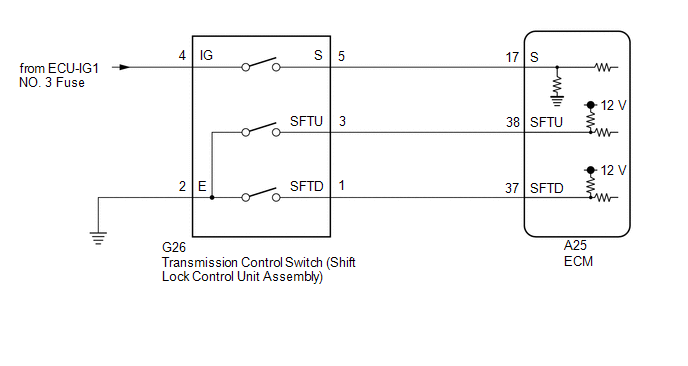
WIRING DIAGRAM
CAUTION / NOTICE / HINT
NOTICE:
Inspect the fuses for circuits related to this system before performing the following procedure.
PROCEDURE
| 1. | READ VALUE USING TECHSTREAM (Shift SW Status (S Range)) |
(a) Connect the Techstream to the DLC3.
(b) Turn the engine switch on (IG).
(c) Turn the Techstream on.
(d) Enter the following menus: Powertrain / Engine / Data List / Shift SW Status (S Range).
(e) Read the Data List according to the display on the Techstream.
Powertrain > Engine > Data List| Tester Display | Measurement Item | Range | Normal Condition | Diagnostic Note |
|---|---|---|---|---|
| Shift SW Status (S Range) | Sport (S) mode select switch status | ON or OFF |
| - |
| Tester Display |
|---|
| Shift SW Status (S Range) |
| Result | Proceed to |
|---|---|
| Data List value is normal | A |
| Data List value is not normal | B |
| B | .gif) | GO TO STEP 6 |
|
.gif)
| 2. | READ VALUE USING TECHSTREAM (SPORT SHIFT UP SW AND SPORT SHIFT DOWN SW) |
(a) Connect the Techstream to the DLC3.
(b) Turn the engine switch on (IG).
(c) Turn the Techstream on.
(d) Enter the following menus: Powertrain / Engine / Data List / Sport Shift Up SW and Sport Shift Down SW.
(e) Read the Data List according to the display on the Techstream.
Powertrain > Engine > Data List| Tester Display | Measurement Item | Range | Normal Condition | Diagnostic Note |
|---|---|---|---|---|
| Sport Shift Up SW | Sport shift up switch status | ON or OFF |
| - |
| Sport Shift Down SW | Sport shift down switch status | ON or OFF |
| - |
| Tester Display |
|---|
| Sport Shift Up SW |
| Sport Shift Down SW |
| Result | Proceed to |
|---|---|
| Data List values are normal | A |
| Data List values are not normal | B |
| A | | PROCEED TO NEXT SUSPECTED AREA SHOWN IN PROBLEM SYMPTOMS TABLE |
|
| 3. | INSPECT TRANSMISSION CONTROL SWITCH (SHIFT LOCK CONTROL UNIT ASSEMBLY) |
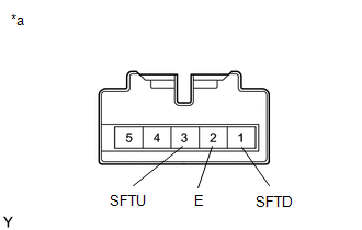
(a) Disconnect the G26 transmission control switch connector.
| (b) Measure the resistance according to the value(s) in the table below. Standard Resistance:
|
|
| NG | | REPLACE TRANSMISSION CONTROL SWITCH (SHIFT LOCK CONTROL UNIT ASSEMBLY) |
|
| 4. | CHECK HARNESS AND CONNECTOR (TRANSMISSION CONTROL SWITCH - BODY GROUND) |
(a) Disconnect the G26 transmission control switch connector.
(b) Measure the resistance according to the value(s) in the table below.
Standard Resistance:
| Tester Connection | Condition | Specified Condition |
|---|---|---|
| G26-2 (E) - Body ground | Always | Below 1 Ω |
| NG | | REPAIR OR REPLACE HARNESS OR CONNECTOR (TRANSMISSION CONTROL SWITCH - BODY GROUND) |
|
| 5. | CHECK HARNESS AND CONNECTOR (TRANSMISSION CONTROL SWITCH - ECM) |
(a) Connect the G26 transmission control switch connector.
(b) Disconnect the A25 ECM connector.
(c) Measure the resistance according to the value(s) in the table below.
Standard Resistance:
| Tester Connection | Condition | Specified Condition |
|---|---|---|
| A25-38 (SFTU) - Body ground | Shift lever held in "+" (Up shift) | Below 1 Ω |
| A25-38 (SFTU) - Body ground | Shift lever not held in "+" (Up shift) | 10 kΩ or higher |
| A25-37 (SFTD) - Body ground | Shift lever held in "-" (Down shift) | Below 1 Ω |
| A25-37 (SFTD) - Body ground | Shift lever not held in "-" (Down shift) | 10 kΩ or higher |
| OK | | PROCEED TO NEXT SUSPECTED AREA SHOWN IN PROBLEM SYMPTOMS TABLE |
| NG | | REPAIR OR REPLACE HARNESS OR CONNECTOR (TRANSMISSION CONTROL SWITCH - ECM) |
| 6. | INSPECT TRANSMISSION CONTROL SWITCH (SHIFT LOCK CONTROL UNIT ASSEMBLY) |
| (a) Disconnect the G26 transmission control switch connector. |
|
(b) Measure the resistance according to the value(s) in the table below.
Standard Resistance:
| Tester Connection | Condition | Specified Condition |
|---|---|---|
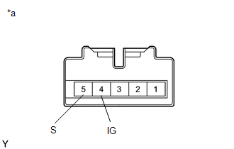
| 4 (IG) - 5 (S) | Shift lever in S, "+" or "-" | Below 1 Ω |
| Shift lever not in S, "+" or "-" | 10 kΩ or higher |
| NG | | REPLACE TRANSMISSION CONTROL SWITCH (SHIFT LOCK CONTROL UNIT ASSEMBLY) |
|
| 7. | CHECK HARNESS AND CONNECTOR (TRANSMISSION CONTROL SWITCH (POWER SOURCE)) |
(a) Disconnect the G26 transmission control switch connector.
(b) Turn the engine switch on (IG).
(c) Measure the voltage according to the value(s) in the table below.
Standard Voltage:
| Tester Connection | Condition | Specified Condition |
|---|---|---|
| G26-4 (IG) - Body ground | Engine switch on (IG) | 11 to 14 V |
| NG | | REPAIR OR REPLACE HARNESS OR CONNECTOR (TRANSMISSION CONTROL SWITCH (POWER SOURCE)) |
|
| 8. | CHECK HARNESS AND CONNECTOR (TRANSMISSION CONTROL SWITCH - ECM) |
(a) Disconnect the G26 transmission control switch connector.
(b) Disconnect the A25 ECM connector.
(c) Measure the resistance according to the value(s) in the table below.
Standard Resistance:
| Tester Connection | Condition | Specified Condition |
|---|---|---|
| G26-5 (S) - A25-17 (S) | Always | Below 1 Ω |
| G26-5 (S) or A25-17 (S) - Body ground and other terminals | Always | 10 kΩ or higher |
| OK | | PROCEED TO NEXT SUSPECTED AREA SHOWN IN PROBLEM SYMPTOMS TABLE |
| NG | | REPAIR OR REPLACE HARNESS OR CONNECTOR (TRANSMISSION CONTROL SWITCH - ECM) |
READ NEXT:
 Lost Communication with ECM/PCM "A" Missing Message (U010087)
DESCRIPTION The engine control unit and transmission control unit are located inside the ECM. The engine control unit intercommunicates with the transmission control unit using CAN communication. If t
Vehicle Control History
VEHICLE CONTROL HISTORY VEHICLE CONTROL HISTORY HINT: A part of the control history can be confirmed using the vehicle control history. Click here
SEE MORE:
Removal
REMOVAL CAUTION / NOTICE / HINT The necessary procedures (adjustment, calibration, initialization, or registration) that must be performed after parts are removed and installed, or replaced during rear shock absorber assembly removal/installation are shown below. Necessary Procedures After Parts Rem
Relay
InspectionINSPECTION PROCEDURE 1. INSPECT ST RELAY (a) Check the resistance. (1) Measure the resistance according to the value(s) in the table below. Standard Resistance: Tester Connection Condition Specified Condition 3 - 5 Battery voltage not applied to terminals 1 and 2 10 kΩ
