Lexus ES: Parking Assist ECU Communication Stop Mode
DESCRIPTION
| Detection Item | Symptom | Trouble Area |
|---|---|---|
| Parking Assist ECU Communication Stop Mode | Any of the following conditions are met:
|
|
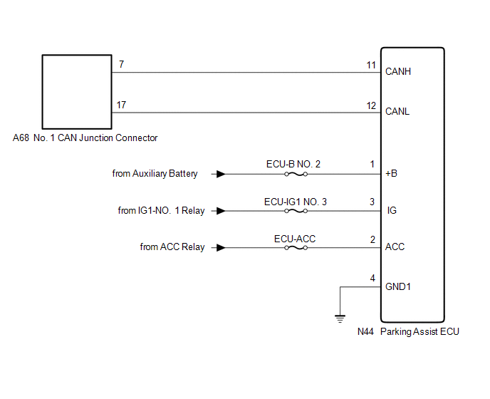
WIRING DIAGRAM
CAUTION / NOTICE / HINT
CAUTION:
When performing the confirmation driving pattern, obey all speed limits and traffic laws.
NOTICE:
-
Because the order of diagnosis is important to allow correct diagnosis, make sure to begin troubleshooting using How to Proceed with Troubleshooting when CAN communication system related DTCs are output.
Click here
.gif)
- Before measuring the resistance of the CAN bus, turn the power switch off and leave the vehicle for 1 minute or more without operating the key or any switches, or opening or closing the doors. After that, disconnect the cable from the negative (-) auxiliary battery terminal and leave the vehicle for 1 minute or more before measuring the resistance.
-
After turning the power switch off, waiting time may be required before disconnecting the cable from the negative (-) auxiliary battery terminal. Therefore, make sure to read the disconnecting the cable from the negative (-) auxiliary battery terminal notices before proceeding with work.
Click here
-
After performing repairs, perform the DTC check procedure and confirm that the DTCs are not output again.
DTC check procedure: Turn the power switch on (IG) and wait for 1 minute or more. Then operate the suspected malfunctioning system and drive the vehicle at 60 km/h (37 mph) or more for 5 minutes or more.
-
After the repair, perform the CAN bus check and check that all the ECUs and sensors connected to the CAN communication system are displayed as normal.
Click here
- Inspect the fuses for circuits related to this system before performing the following procedure.
HINT:
- Before disconnecting related connectors for inspection, push in on each connector body to check that the connector is not loose or disconnected.
- When a connector is disconnected, check that the terminals and connector body are not cracked, deformed or corroded.
PROCEDURE
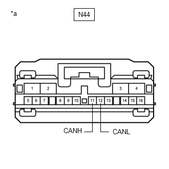
| 1. | CHECK FOR OPEN IN CAN BUS LINES (PARKING ASSIST ECU BRANCH LINE) |
(a) Disconnect the cable from the negative (-) auxiliary battery terminal.
(b) Disconnect the N44 parking assist ECU connector.
| (c) Measure the resistance according to the value(s) in the table below. Standard Resistance:
|
|
| NG | .gif) | REPAIR OR REPLACE CAN BRANCH LINES OR CONNECTOR (PARKING ASSIST ECU) |
|
.gif)
| 2. | CHECK HARNESS AND CONNECTOR (POWER SOURCE CIRCUIT) |
| (a) Measure the resistance according to the value(s) in the table below. Standard Resistance:
|
|
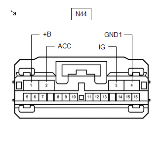
(b) Reconnect the cable to the negative (-) auxiliary battery terminal.
(c) Measure the voltage according to the value(s) in the table below.
Standard Voltage:
| Tester Connection | Condition | Specified Condition |
|---|---|---|
| N44-1 (+B) - Body ground | Power switch off | 11 to 14 V |
| N44-2 (ACC) - Body ground | Power switch on (ACC) | 11 to 14 V |
| N44-3 (IG) - Body ground | Power switch on (IG) | 11 to 14 V |
| OK | | REPLACE PARKING ASSIST ECU |
| NG | | REPAIR OR REPLACE HARNESS OR CONNECTOR (POWER SOURCE CIRCUIT) |
READ NEXT:
 Bus Buffer ECU Communication Stop Mode
DESCRIPTION Detection Item Symptom Trouble Area Bus Buffer ECU Communication Stop Mode Any of the following conditions are met:
Communication stop for "Accessory Gateway" is indicated
Active Noise Control ECU Communication Stop Mode
DESCRIPTION Detection Item Symptom Trouble Area Active Noise Control ECU Communication Stop Mode Any of the following conditions are met:
Communication stop for "Active Noise Control"
Blind Spot Monitor Sensor Communication Stop Mode
DESCRIPTION Detection Item Symptom Trouble Area Blind Spot Monitor Sensor Communication Stop Mode Any of the following conditions are met:
Communication stop for "Blind Spot Monitor Ma
SEE MORE:
Discharging
DISCHARGING PROCEDURE 1. DISCHARGING (WHEN USING THE LI-ION BATTERY DISCHARGER) CAUTION: Be sure to wear insulated gloves and protective goggles. NOTICE: Make sure to observe the following points when using the Li-ion battery discharger.
Set it in a secure, flat place.
Set it in a dry place pro
Voice Guidance Circuit between Radio Receiver and Stereo Component Amplifier
DESCRIPTION Using this circuit, the radio receiver assembly sends signals to the stereo component amplifier assembly. WIRING DIAGRAM PROCEDURE 1. CHECK HARNESS AND CONNECTOR (RADIO RECEIVER ASSEMBLY - STEREO COMPONENT AMPLIFIER ASSEMBLY) (a) Disconnect the G7 radio receiver assembly connec
