Lexus ES: System Diagram
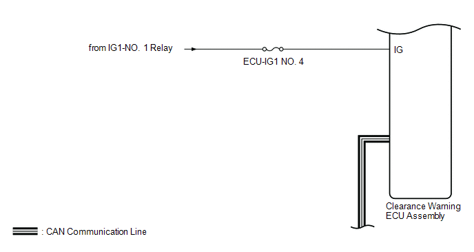
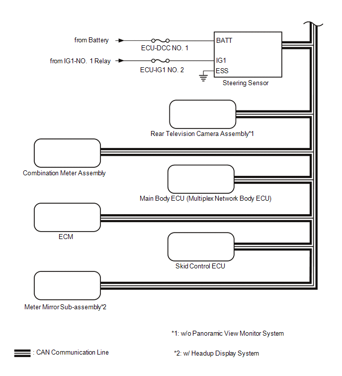
SYSTEM DIAGRAM
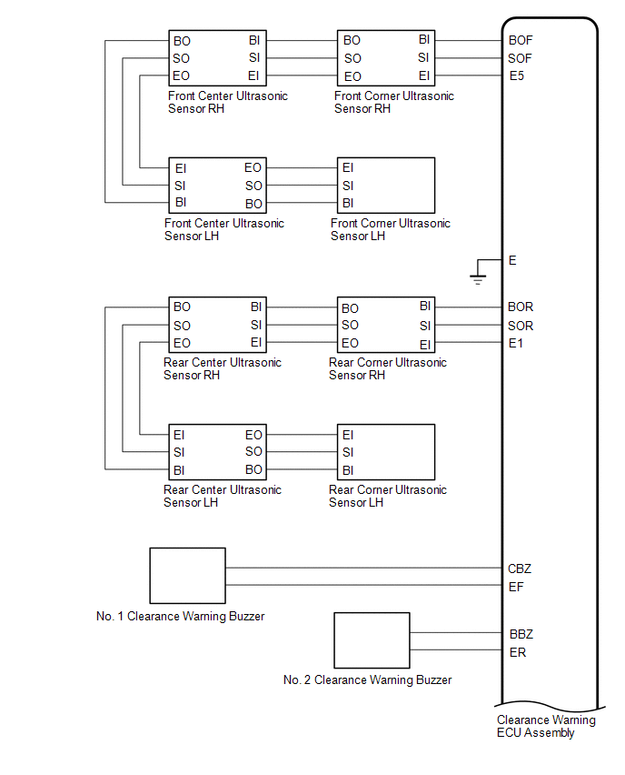 for 12.3 inch display w/o Panoramic View Monitor System
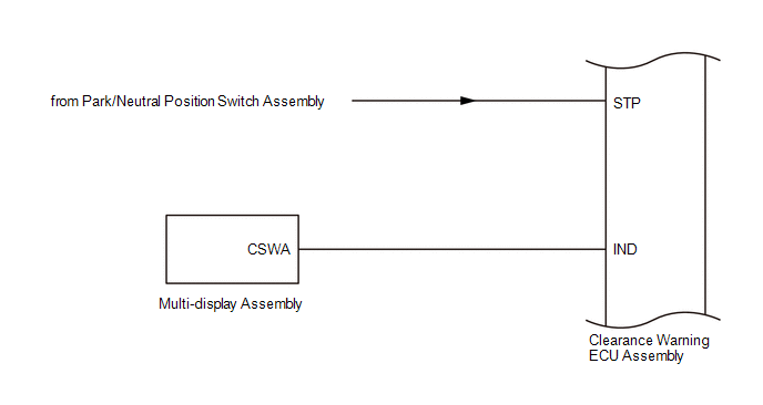
 w/ Blind Spot Monitor System
 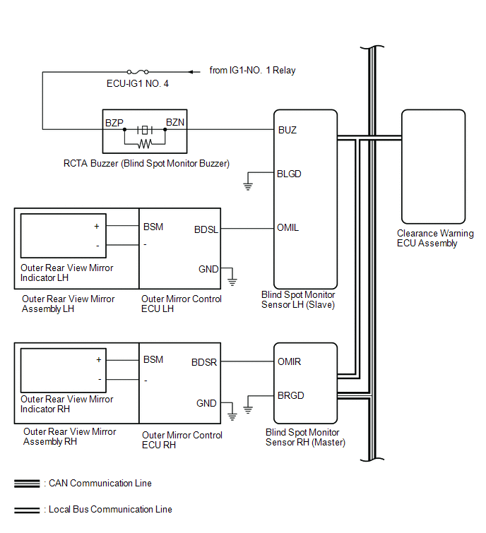 w/ Panoramic View Monitor System
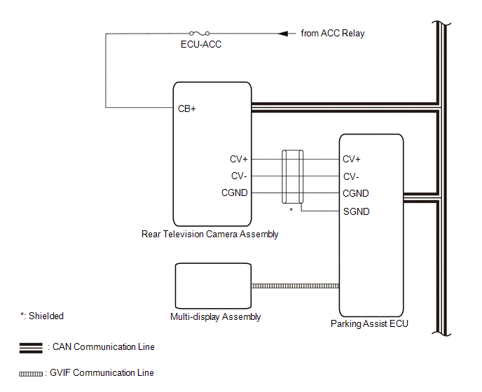
READ NEXT:
 Terminals Of Ecu
TERMINALS OF ECU CLEARANCE WARNING ECU ASSEMBLY (a) Disconnect the N41 clearance warning ECU assembly connector. (b) Measure the voltage and resistance on the wire harness side connector according to
The Display of the Multi-display does not Switched
DESCRIPTION The multi-display receives a signal from the clearance warning ECU assembly to change the display screen. WIRING DIAGRAM PROCEDURE 1. CHECK HARNESS AND CONNECTOR (CLEARANCE WARNING
Control Module Communication Bus "A" Off (U0073,U0126,U0129,U0140,U0155)
DESCRIPTION These DTCs are stored when the clearance warning ECU assembly cannot receive and recognize several signals via the CAN communication line. DTC No. Detection Item DTC Detection Condi
SEE MORE:
On-vehicle Inspection
ON-VEHICLE INSPECTION PROCEDURE 1. INSPECT HOOD SUB-ASSEMBLY (a) Check that the clearance measurements of areas a through d are within each standard range. Standard Clearance Area Measurement Area Measurement a 2.85 to 5.85 mm (0.112 to 0.230 in.) b 1.85 to 5.85 mm (0.0728 to 0.2
Evaporative Emission System Leak Detected (Large Leak) (P045500,P045600)
DTC SUMMARY DTC No. Detection Item DTC Detection Condition Trouble Area MIL Memory Note P045500 Evaporative Emission System Leak Detected (Large Leak) Leak detection pump creates negative pressure (vacuum) in EVAP system and EVAP system pressure is measured. Reference pressure
© 2016-2026 Copyright www.lexguide.net
