Lexus ES: Installation
INSTALLATION
PROCEDURE
1. INSTALL SLIDING ROOF OR REMOVABLE ROOF HOUSING SUB-ASSEMBLY
(a) Pass a string under the windshield outside moulding as shown in the illustration.
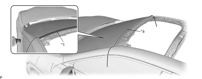
| *1 | Windshield Outside Moulding | - | - |
| *a | String | - | - |
(b) Engage the 2 guides.
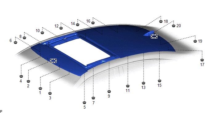
(c) Temporarily install the sliding roof or removable roof housing sub-assembly with the 20 nuts.
(d) Tighten the 20 nuts to install the sliding roof or removable roof housing sub-assembly.
HINT:
Tighten the nuts in the order shown in the illustration.
Torque:
8.0 N·m {82 kgf·cm, 71 in·lbf}
(e) Apply soapy water to the windshield outside moulding.
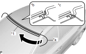
| *1 | Windshield Outside Moulding |
| *a | String |
| *b | Correct |
| *c | Incorrect |
.png) | String Pulling Direction |
(f) Slowly pull out the string to install the windshield outside moulding to the correct position.
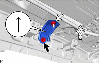
2. INSTALL REAR SLIDING ROOF HOUSING MOUNTING BRACKET LH
(a) Install the rear sliding roof housing mounting bracket LH with the bolt and nut.
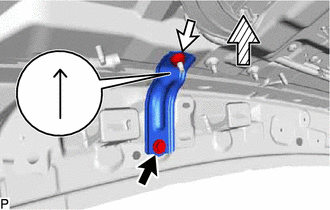
.png) | Bolt |
.png) | Nut |
.png) | Upper Side of Vehicle |
Torque:
8.0 N·m {82 kgf·cm, 71 in·lbf}
HINT:
Make sure to install the rear sliding roof housing mounting bracket LH with its arrow facing the upper side of the vehicle.
3. INSTALL REAR SLIDING ROOF HOUSING MOUNTING BRACKET RH
HINT:
Use the same procedure as for the LH side.
4. INSTALL CENTER SLIDING ROOF HOUSING MOUNTING BRACKET LH
(a) Install the center sliding roof housing mounting bracket LH with the 2 bolts and 2 nuts.
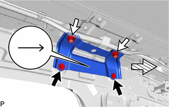
| | Bolt |
| | Nut |
| | Front of Vehicle |
Torque:
8.0 N·m {82 kgf·cm, 71 in·lbf}
HINT:
Make sure to install the center sliding roof housing mounting bracket with its arrow facing the front of the vehicle.
5. INSTALL CENTER SLIDING ROOF HOUSING MOUNTING BRACKET RH
HINT:
Use the same procedure as for the LH side.
6. INSTALL FRONT SLIDING ROOF HOUSING MOUNTING BRACKET LH
(a) Install the front sliding roof housing mounting bracket LH with the bolt and nut.
| | Bolt |
| | Nut |
| | Upper Side of Vehicle |
Torque:
8.0 N·m {82 kgf·cm, 71 in·lbf}
HINT:
Make sure to install the front sliding roof housing mounting bracket LH with its arrow facing the upper side of the vehicle.
7. INSTALL FRONT SLIDING ROOF HOUSING MOUNTING BRACKET RH
HINT:
Use the same procedure as for the LH side.
8. INSTALL SLIDING ROOF GLASS SUB-ASSEMBLY
(a) Using a T25 "TORX" socket wrench, temporarily install the sliding roof glass sub-assembly with the 6 screws.
(b) Perform a level check.
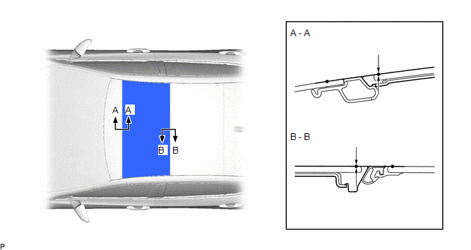
(1) Check the difference in level of the sliding roof glass sub-assembly when the sliding roof glass sub-assembly is fully closed.
| Area | Measurement | Area | Measurement |
|---|---|---|---|
| A-A | -1.0 to 2.0 mm (-0.0394 to 0.0787 in.) | B-B | -1.0 to 2.4 mm (-0.0394 to 0.0945 in.) |
(c) Perform a gap check.
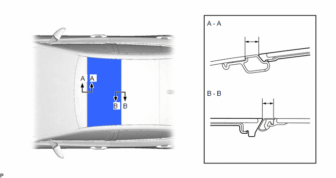
(1) Check the gap between the sliding roof glass sub-assembly and sliding roof housing assembly.
| Area | Measurement | Area | Measurement |
|---|---|---|---|
| A-A | 10.9 to 12.9 mm (0.4291 to 0.5079 in.) | B-B | 7.7 to 10.7 mm (0.3031 to 0.4213 in.) |
(d) After adjusting the sliding roof glass sub-assembly, using a T25 "TORX" socket wrench, tighten the 6 screws.
Torque:
5.0 N·m {51 kgf·cm, 44 in·lbf}
9. CHECK FOR WATER LEAK
(a) After adjusting the sliding roof glass sub-assembly, check for water leakage into the vehicle interior.
(b) If there are any leaks, readjust the sliding roof glass sub-assembly.
10. INSTALL TELEPHONE ANTENNA ASSEMBLY
Click here .gif)
11. INSTALL CURTAIN SHIELD AIRBAG ASSEMBLY LH
Click here
12. INSTALL CURTAIN SHIELD AIRBAG ASSEMBLY RH
HINT:
Use the same procedure as for the LH side.
13. INSTALL SLIDING ROOF SIDE GARNISH LH (for Front Side)
(a) Engage the 5 claws to install the sliding roof side garnish LH.
14. INSTALL SLIDING ROOF SIDE GARNISH RH (for Front Side)
HINT:
Use the same procedure as for the LH side.
15. INSTALL SLIDING ROOF SIDE GARNISH LH (for Rear Side)
(a) Install the sliding roof side garnish LH.
16. INSTALL SLIDING ROOF SIDE GARNISH RH (for Rear Side)
HINT:
Use the same procedure as for the LH side.
17. INSTALL FRONT SLIDING ROOF GARNISH LH
(a) Move the sliding roof glass sub-assembly to the fully tilted up position.
(b) Install the front sliding roof garnish LH.
18. INSTALL FRONT SLIDING ROOF GARNISH RH
HINT:
Use the same procedure as for the LH side.
19. INITIALIZE PANORAMIC MOON ROOF SYSTEM
Click here
20. CHECK PANORAMIC MOON ROOF SYSTEM
Click here
READ NEXT:
 Components
COMPONENTS ILLUSTRATION *1 SLIDING ROOF OR REMOVABLE ROOF PANEL SUB-ASSEMBLY *2 SLIDING ROOF SIDE GARNISH LH *3 SLIDING ROOF SIDE GARNISH RH *4 SLIDING ROOF WEATHERSTRIP *5 S
Removal
REMOVAL CAUTION / NOTICE / HINT The necessary procedures (adjustment, calibration, initialization or registration) that must be performed after parts are removed and installed, or replaced during slid
SEE MORE:
Front Camera Response Malfunction (C2A6D)
DESCRIPTION During self diagnosis of the parking assist ECU, the parking assist ECU sends display mode ID signals to the front television camera assembly. This DTC is stored when the output of the front television camera assembly does not match the expected output. DTC No. Detection Item DTC
PBD/PTL Pulse Sensor (B2222,B2225)
DESCRIPTION DTC B2222 is output when there is a malfunction in the door pulse sensor system inside the luggage closer motor assembly and a normal waveform is not input to the door pulse sensor during a power trunk lid operation. Also, this DTC is output when there is a malfunction in the power trunk
