Lexus ES: Terminals Of Ecu
TERMINALS OF ECU
CLEARANCE WARNING ECU ASSEMBLY

(a) Disconnect the N41 clearance warning ECU assembly connector.
(b) Measure the voltage and resistance on the wire harness side connector according to the value(s) in the table below.
| Terminal No. (Symbol) | Wiring Color | Terminal Description | Condition | Specified Condition |
|---|---|---|---|---|
| N41-1 (IG) - N41-30 (E) | B - W-B | IG power source signal | Engine switch off | Below 1 V |
| Engine switch on (IG) | 11 to 14 V | |||
| N41-30 (E) - Body ground | W-B - Body ground | Ground | Always | Below 1 Ω |
(c) Reconnect the N41 clearance warning ECU assembly connector.
(d) Measure the voltage and check for pulses according to the value(s) in the table below.
| Terminal No. (Symbol) | Wiring Color | Terminal Description | Condition | Specified Condition |
|---|---|---|---|---|
| N41-4 (BOF) - N41-30 (E) | R - W-B | Power source for front sensor circuit | Engine switch off | Below 1 V |
| 11 to 14 V | |||
| N41-6 (E5) - N41-30 (E) | W - W-B | Ground for front clearance sonar | Always | Below 1 Ω |
| N41-8 (SOF) - N41-30 (E) | B - W-B | Front sensor communication signal (Front clearance sonar sensor) |
| Pulse generation (Refer to waveform 1) |
| N41-14 (CBZ) - N41-13 (EF) | LG - L | No. 1 clearance warning buzzer signal | Buzzer sounding | Pulse generation (Refer to waveform 2) |
| N41-15 (BBZ) - N41-16 (ER) | G - BE | No. 2 clearance warning buzzer signal | Buzzer sounding | Pulse generation (Refer to waveform 2) |
| N41-22 (BOR) - N41-30 (E) | LG - W-B | Power source for rear sensor circuit | Engine switch off | Below 1 V |
| 11 to 14 V | |||
| N41-23 (E1) - N41-30 (E) | GR - W-B | Ground for rear clearance sonar | Always | Below 1 Ω |
| N41-24 (SOR) - N41-30 (E) | SB - W-B | Rear sensor communication signal (Rear clearance sonar sensor) |
| Pulse generation (Refer to waveform 1) |
| N41-28 (STP) - N41-30 (E)* | V - W-B | Reverse signal input |
| 11 to 14 V |
| Below 1 V | |||
| N41-31 (IND) - N41-30 (E)* | P - W-B | Display select signal |
| Below 3 V |
| 8 V or higher |
- *: w/o Panoramic View Monitor System
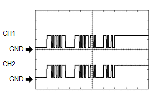
(e) Using an oscilloscope, check waveform 1.
(1) Waveform 1 (Reference)
| Item | Content |
|---|---|
| Measurement terminal |
|
| Measurement setting | 5 V/DIV., 1 ms./DIV. |
| Condition |
|
HINT:
The waveforms for CH1 and CH2 are same.
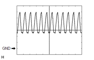
(f) Using an oscilloscope, check waveform 2.
(1) Waveform 2 (Reference)
| Item | Content |
|---|---|
| Measurement terminal | N41-14 (CBZ) - N41-13 (EF) N41-15 (BBZ) - N41-16 (ER) |
| Measurement setting | 2 V/DIV., 500 μs./DIV. |
| Condition | Buzzer sounding |
HINT:
The amplitude of the waveform changes according to the set volume.
BLIND SPOT MONITOR SENSOR RH (w/ Blind Spot Monitor System)
Click here .gif)
BLIND SPOT MONITOR SENSOR LH (w/ Blind Spot Monitor System)
Click here
REAR TELEVISION CAMERA ASSEMBLY (w/ Panoramic View Monitor System)
Click here
READ NEXT:
 The Display of the Multi-display does not Switched
DESCRIPTION The multi-display receives a signal from the clearance warning ECU assembly to change the display screen. WIRING DIAGRAM PROCEDURE 1. CHECK HARNESS AND CONNECTOR (CLEARANCE WARNING
Control Module Communication Bus "A" Off (U0073,U0126,U0129,U0140,U0155)
DESCRIPTION These DTCs are stored when the clearance warning ECU assembly cannot receive and recognize several signals via the CAN communication line. DTC No. Detection Item DTC Detection Condi
CAN Communication Failure (Message Registry) (U1000)
DESCRIPTION If DTC U1000 is stored frequently, duplicate the conditions that cause the problem symptoms and perform troubleshooting again even if the DTC is not output when rechecking for DTCs. DTC
SEE MORE:
Removal
REMOVAL CAUTION / NOTICE / HINT The necessary procedures (adjustment, calibration, initialization, or registration) that must be performed after parts are removed and installed, or replaced during power window regulator motor assembly removal/installation are shown below. Necessary Procedure After P
Customize Parameters
CUSTOMIZE PARAMETERS CUSTOMIZE LTA NOTICE:
When the customer requests a change in a function, first make sure that the function can be customized.
Be sure to make a note of the current settings before customizing.
When troubleshooting a function, first make sure that the function is set to th
