Lexus ES: Stereo Jack Adapter Light does not Illuminate
DESCRIPTION
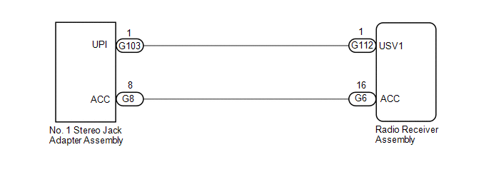
Power is supplied to the No. 1 stereo jack adapter assembly illumination from the radio receiver assembly.
WIRING DIAGRAM
CAUTION / NOTICE / HINT
NOTICE:
-
Depending on the parts that are replaced during vehicle inspection or maintenance, performing initialization, registration or calibration may be needed. Refer to Precaution for Audio and Visual System.
Click here
.gif)
-
When replacing the radio receiver assembly, always replace it with a new one. If a radio receiver assembly which was installed to another vehicle is used, the following may occur:
- A communication malfunction DTC may be stored.
- The radio receiver assembly may not operate normally.
PROCEDURE
| 1. | CHECK HARNESS AND CONNECTOR (NO. 1 STEREO JACK ADAPTER ASSEMBLY ILLUMINATION POWER SOURCE) |
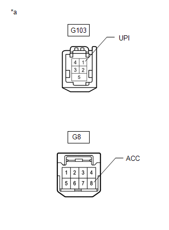
(a) Disconnect the G103 and G8 No. 1 stereo jack adapter assembly connectors.
| (b) Measure the voltage according to the value(s) in the table below. Standard Voltage:
|
|
| OK | .gif) | REPLACE NO. 1 STEREO JACK ADAPTER ASSEMBLY |
|
.gif)
| 2. | CHECK HARNESS AND CONNECTOR (RADIO RECEIVER ASSEMBLY - NO. 1 STEREO JACK ADAPTER ASSEMBLY) |
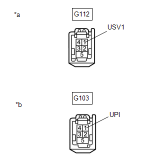
(a) Disconnect the G112 radio receiver assembly connector.
(b) Disconnect the G103 No. 1 stereo jack adapter assembly connector.
| (c) Measure the resistance according to the value(s) in the table below. Standard Resistance:
|
|
| NG | | REPAIR OR REPLACE HARNESS OR CONNECTOR |
|
| 3. | CHECK HARNESS AND CONNECTOR (RADIO RECEIVER ASSEMBLY - NO. 1 STEREO JACK ADAPTER ASSEMBLY) |
(a) Disconnect the G6 radio receiver assembly connector.
(b) Disconnect the G8 No. 1 stereo jack adapter assembly connector.
(c) Measure the resistance according to the value(s) in the table below.
Standard Resistance:
| Tester Connection | Condition | Specified Condition |
|---|---|---|
| G8-8 (ACC) - G6-16 (ACC) | Always | Below 1 Ω |
| G8-8 (ACC) or G6-16 (ACC) - Body ground | Always | 10 kΩ or higher |
| OK | | REPLACE RADIO RECEIVER ASSEMBLY |
| NG | | REPAIR OR REPLACE HARNESS OR CONNECTOR |
READ NEXT:
 Switch Lights of Remote Touch Always Illuminate or cannot be Controlled Using Rheostat
DESCRIPTION Power is supplied to the remote touch (remote operation controller assembly) illumination when the light control switch is in the tail or head position. HINT:
When the remote touch (rem
Switch Lights of Remote Touch do not Illuminate
DESCRIPTION Power is supplied to the remote touch (remote operation controller assembly) illumination when the light control switch is in the tail or head position. WIRING DIAGRAM CAUTION / NOTICE /
Switch Operation of Remote Touch not Accepted
CAUTION / NOTICE / HINT NOTICE:
Depending on the parts that are replaced during vehicle inspection or maintenance, performing initialization, registration or calibration may be needed. Refer to Pre
SEE MORE:
Starting System
Parts LocationPARTS LOCATION ILLUSTRATION *1 STARTER ASSEMBLY *2 ECM *3 ENGINE ROOM RELAY BLOCK AND JUNCTION BLOCK ASSEMBLY - ST RELAY - FL MAIN FUSE - ST FUSE *4 PARK/NEUTRAL POSITION SWITCH ASSEMBLY ILLUSTRATION *1 ENGINE SWITCH *2 CERTIFICATION ECU (SMART KEY ECU
Installation
INSTALLATION PROCEDURE 1. INSTALL FLOW SHUTTING VALVE (WATER BY-PASS HOSE ASSEMBLY) (a) Connect the flow shutting valve (water by-pass hose assembly) to the transmission oil cooler and slide the clip to secure it. *a 2 to 7 mm (0.0787 to 0.276 in.) *b Paint Mark *c 45° (Tabs of Clip
