Lexus ES: Starting System
Parts Location
PARTS LOCATION
ILLUSTRATION
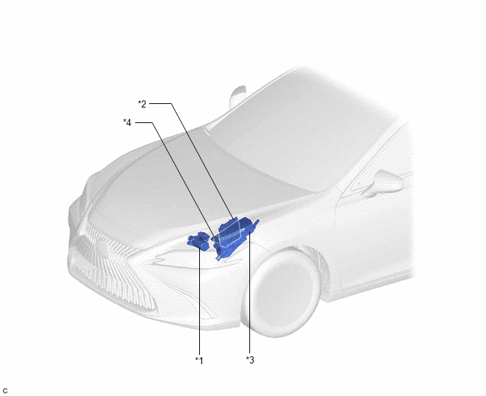
| *1 | STARTER ASSEMBLY | *2 | ECM |
| *3 | ENGINE ROOM RELAY BLOCK AND JUNCTION BLOCK ASSEMBLY - ST RELAY - FL MAIN FUSE - ST FUSE | *4 | PARK/NEUTRAL POSITION SWITCH ASSEMBLY |
ILLUSTRATION
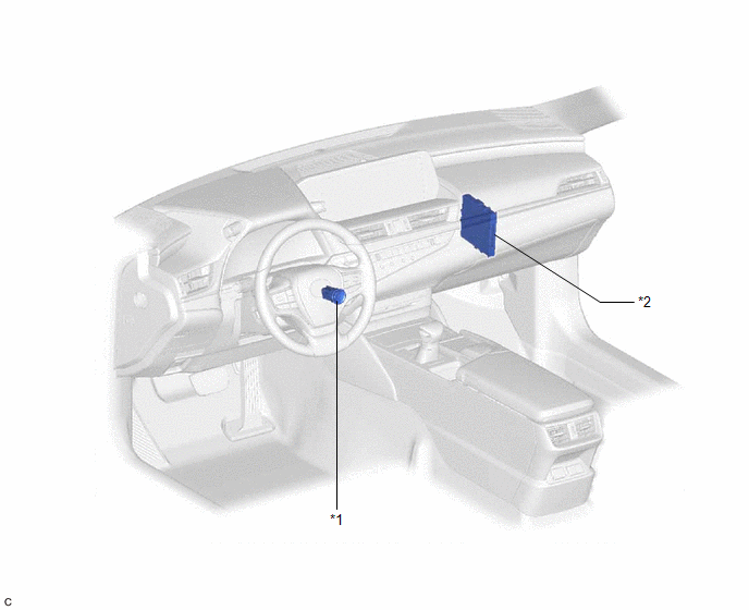
| *1 | ENGINE SWITCH | *2 | CERTIFICATION ECU (SMART KEY ECU ASSEMBLY) |
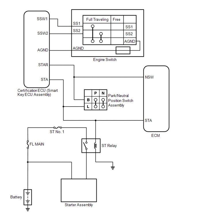
System Diagram
SYSTEM DIAGRAM
READ NEXT:
 Coolant
ComponentsCOMPONENTS ILLUSTRATION *1 RADIATOR CAP SUB-ASSEMBLY *2 RADIATOR DRAIN COCK PLUG *3 NO. 1 ENGINE UNDER COVER - - ReplacementREPLACEMENT CAUTION / NOTICE / HINT CAUTI
SEE MORE:
Removal
REMOVAL CAUTION / NOTICE / HINT The necessary procedures (adjustment, calibration, initialization, or registration) that must be performed after parts are removed and installed, or replaced during engine coolant temperature sensor removal/installation are shown below. Necessary Procedures After Part
On-vehicle Inspection
ON-VEHICLE INSPECTION CAUTION / NOTICE / HINT CAUTION: To prevent injury due to contact with an operating V-ribbed belt or cooling fan, keep your hands and clothing away from the V-ribbed belt and cooling fan when working in the engine compartment with the engine running or the engine switch on (IG)
© 2016-2026 Copyright www.lexguide.net
