Lexus ES: Installation
INSTALLATION
PROCEDURE
1. INSTALL FLOW SHUTTING VALVE (WATER BY-PASS HOSE ASSEMBLY)
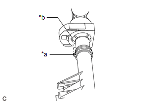
(a) Connect the flow shutting valve (water by-pass hose assembly) to the transmission oil cooler and slide the clip to secure it.
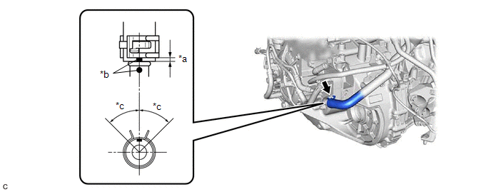
| *a | 2 to 7 mm (0.0787 to 0.276 in.) | *b | Paint Mark |
| *c | 45° (Tabs of Clip Installation Area) | - | - |
NOTICE:
- Make sure to slide the flow shutting valve (water by-pass hose assembly) until it contacts the hose stopper of the transmission oil cooler.
- Make sure to align the paint mark of the flow shutting valve (water by-pass hose assembly) with the paint mark of the transmission oil cooler.
- Make sure that the tabs of the clip are within the area shown in the illustration.
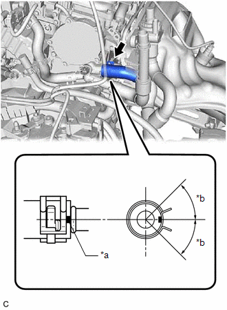
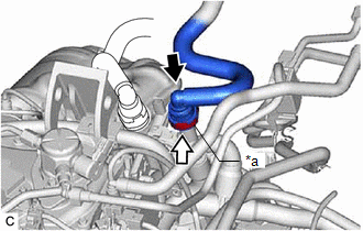
| (b) Connect the flow shutting valve (water by-pass hose assembly) to the water by-pass outlet sub-assembly and slide the clip to secure it. NOTICE:
|
|
(c) Install the water hose clamp bracket with the 2 bolts.
Torque:
13 N·m {133 kgf·cm, 10 ft·lbf}
(d) Engage the 2 clamps to connect the wire harness.
(e) Connect the flow shutting valve (water by-pass hose assembly) with the bolt.
Torque:
19 N·m {194 kgf·cm, 14 ft·lbf}
(f) Connect the No. 2 water by-pass pipe sub-assembly with the bolt.
Torque:
19 N·m {194 kgf·cm, 14 ft·lbf}
(g) Connect the inlet heater hose connector to the flow shutting valve (water by-pass hose assembly).
NOTICE:
Check that there is no damage or foreign matter on the connecting parts of the water lines.
| (1) Align the protrusions of the inlet heater hose connector with the cutouts in the flow shutting valve (water by-pass hose assembly) and push them together until the inlet heater hose connector makes a "click" sound. |
|
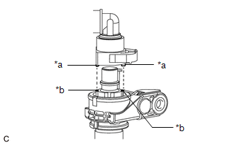
(2) Push in the retainer.
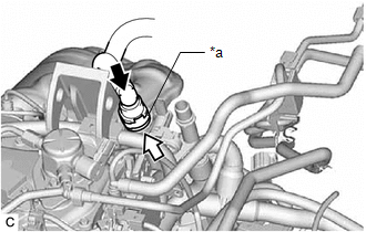
| *a | Retainer |
.png) | Push |
.png) | Push in |
(3) Check that the flow shutting valve (water by-pass hose assembly) and inlet heater hose connector are securely connected by pulling on them.
(h) Connect the outlet heater hose connector to the No. 2 water by-pass pipe sub-assembly.
NOTICE:
Check that there is no damage or foreign matter on the connecting parts of the water lines.
| (1) Align the protrusion of the No. 2 water by-pass pipe sub-assembly with the cutout in the outlet heater hose connector and push them together until the outlet heater hose connector makes a "click" sound. |
|
(2) Push in the retainer.
| *a | Retainer |
| | Push |
| | Push in |
(3) Check that the No. 2 water by-pass pipe sub-assembly and outlet heater hose connector are securely connected by pulling on them.
(i) Engage the clamp to connect the engine wire harness to the water hose clamp bracket.
(j) Connect the 3 connectors.
(k) Engage the clamp to connect the vacuum hose to the engine wire harness.
2. INSTALL FLOW SHUTTING VALVE (NO. 1 WATER BY-PASS HOSE)
Click here .gif)
READ NEXT:
 Components
COMPONENTS ILLUSTRATION *1 FRONT WHEEL OPENING EXTENSION PAD LH *2 FRONT WHEEL OPENING EXTENSION PAD RH *3 NO. 1 ENGINE UNDER COVER *4 NO. 2 ENGINE UNDER COVER ASSEMBLY N*m
On-vehicle Inspection
ON-VEHICLE INSPECTION CAUTION / NOTICE / HINT CAUTION: Do not remove the radiator cap sub-assembly while the engine and radiator assembly are still hot. Pressurized, hot engine coolant and steam may b
SEE MORE:
Fail-safe Chart
FAIL-SAFE CHART PROTECTION FUNCTION (a) The windshield wiper motor assembly operates the following protection functions if it detects an abnormal condition, in order to protect the wiper and washer system. Item Protection Content Conditions to Return to Normal Condition Overheat protectio
DC/DC Converter Temperature Sensor "A" Circuit Short to Ground (P0C3811,P0C3815,P0C3D11,P0C3D15)
DESCRIPTION The motor generator control ECU (MG ECU) located in the inverter with converter assembly detects the temperature of the boost converter using the temperature sensor built into the boost converter. The motor generator control ECU (MG ECU) detects malfunctions in the boost converter temper
