Lexus ES: Sound Signal Circuit between Radio Receiver and Stereo Component Amplifier
DESCRIPTION
The radio receiver assembly sends a sound signal to the stereo component amplifier assembly via this circuit.
The sound signal that has been sent is amplified by the stereo component amplifier assembly, and then is sent to the speakers.
If there is an open or short in the circuit, sound cannot be heard from the speakers even if there is no malfunction in the stereo component amplifier assembly or speakers.
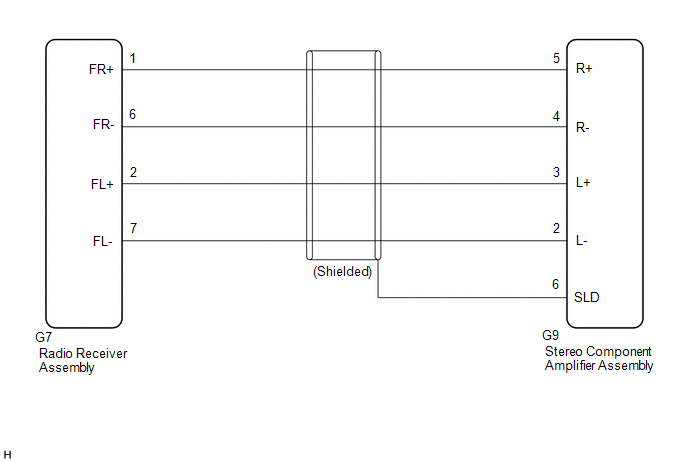
WIRING DIAGRAM
PROCEDURE
| 1. | CHECK HARNESS AND CONNECTOR (RADIO RECEIVER ASSEMBLY - STEREO COMPONENT AMPLIFIER ASSEMBLY) |
(a) Disconnect the G7 radio receiver assembly connector.
(b) Disconnect the G9 stereo component amplifier assembly connector.
(c) Measure the resistance according to the value(s) in the table below.
Standard Resistance:
| Tester Connection | Condition | Specified Condition |
|---|---|---|
| G7-1 (FR+) - G9-5 (R+) | Always | Below 1 Ω |
| G7-6 (FR-) - G9-4 (R-) | Always | Below 1 Ω |
| G7-2 (FL+) - G9-3 (L+) | Always | Below 1 Ω |
| G7-7 (FL-) - G9-2 (L-) | Always | Below 1 Ω |
| G9-6 (SLD) - Body ground | Always | 10 kΩ or higher |
| G7-1 (FR+) or G9-5 (R+) - Body ground | Always | 10 kΩ or higher |
| G7-6 (FR-) or G9-4 (R-) - Body ground | Always | 10 kΩ or higher |
| G7-2 (FL+) or G9-3 (L+) - Body ground | Always | 10 kΩ or higher |
| G7-7 (FL-) or G9-2 (L-) - Body ground | Always | 10 kΩ or higher |
| OK |  | PROCEED TO NEXT SUSPECTED AREA SHOWN IN PROBLEM SYMPTOMS TABLE |
.gif)
| NG | | REPAIR OR REPLACE HARNESS OR CONNECTOR |
READ NEXT:
 Sound Signal Circuit between Radio Receiver and Stereo Jack Adapter
DESCRIPTION The No. 1 stereo jack adapter assembly sends the sound signal from an external device to the radio receiver assembly via this circuit. WIRING DIAGRAM PROCEDURE 1. CHECK HARNESS AND
Speaker Circuit
DESCRIPTION If there is a short in a speaker circuit, the stereo component amplifier assembly detects it and stops output to the speakers. Thus sound cannot be heard from the speakers even if there is
Steering Pad Switch Circuit
DESCRIPTION This circuit sends an operation signal from the steering pad switch assembly to the radio receiver assembly. If there is an open in the circuit, the audio system cannot be operated using t
SEE MORE:
Reassembly
REASSEMBLY PROCEDURE 1. INSTALL FUEL PUMP HINT: Perform "Inspection After Repair" after replacing the fuel pump. Click here (a) for Type A: (1) Apply gasoline to a new O-ring. Then install the O-ring and fuel pump spacer to the fuel pump. *1 O-ring *2 Fuel Pump Spacer
Confirm Cellular Phone Functionality
PROCEDURE 1. CHECK CUSTOMER'S CELLULAR PHONE COMPATIBILITY (a) Check if the cellular phone is compatible (Refer to http://www.lexus.com/MobileLink/). Result Proceed to Cellular phone is compatible. A Cellular phone is not compatible. B HINT: It is important to check the
