Lexus ES: Sound Signal Circuit between Radio Receiver and Stereo Jack Adapter
DESCRIPTION
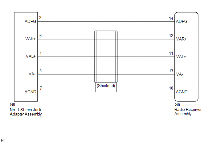
The No. 1 stereo jack adapter assembly sends the sound signal from an external device to the radio receiver assembly via this circuit.
WIRING DIAGRAM
PROCEDURE
| 1. | CHECK HARNESS AND CONNECTOR (RADIO RECEIVER ASSEMBLY - NO. 1 STEREO JACK ADAPTER ASSEMBLY) |
(a) Disconnect the G6 radio receiver assembly connector.
(b) Disconnect the G8 No. 1 stereo jack adapter assembly connector.
(c) Measure the resistance according to the value(s) in the table below.
Standard Resistance:
| Tester Connection | Condition | Specified Condition |
|---|---|---|
| G6-14 (ADPG) - G8-2 (ADPG) | Always | Below 1 Ω |
| G6-10 (AGND) - G8-7 (AGND) | Always | Below 1 Ω |
| G6-12 (VAR+) - G8-6 (VAR+) | Always | Below 1 Ω |
| G6-11 (VAL+) - G8-1 (VAL+) | Always | Below 1 Ω |
| G6-13 (VA-) - G8-5 (VA-) | Always | Below 1 Ω |
| G6-14 (ADPG) or G8-2 (ADPG) - Body ground | Always | 10 kΩ or higher |
| G6-10 (AGND) or G8-7 (AGND) - Body ground | Always | 10 kΩ or higher |
| G6-12 (VAR+) or G8-6 (VAR+) - Body ground | Always | 10 kΩ or higher |
| G6-11 (VAL+) or G8-1 (VAL+) - Body ground | Always | 10 kΩ or higher |
| G6-13 (VA-) or G8-5 (VA-) - Body ground | Always | 10 kΩ or higher |
| OK |  | PROCEED TO NEXT SUSPECTED AREA SHOWN IN PROBLEM SYMPTOMS TABLE |
.gif)
| NG | | REPAIR OR REPLACE HARNESS OR CONNECTOR |
READ NEXT:
 Speaker Circuit
DESCRIPTION If there is a short in a speaker circuit, the stereo component amplifier assembly detects it and stops output to the speakers. Thus sound cannot be heard from the speakers even if there is
Steering Pad Switch Circuit
DESCRIPTION This circuit sends an operation signal from the steering pad switch assembly to the radio receiver assembly. If there is an open in the circuit, the audio system cannot be operated using t
Stereo Jack Adapter Light does not Illuminate
DESCRIPTION Power is supplied to the No. 1 stereo jack adapter assembly illumination from the radio receiver assembly. WIRING DIAGRAM CAUTION / NOTICE / HINT NOTICE:
Depending on the parts that ar
SEE MORE:
ECU Malfunction (B1003)
DESCRIPTION DTC No. Detection Item DTC Detection Condition Trouble Area Note B1003 ECU Malfunction A malfunction in the non-volatile storage of the central gateway ECU (network gateway ECU) is detected. Central gateway ECU (network gateway ECU) - PROCEDURE 1. RECONFIR
How To Proceed With Troubleshooting
CAUTION / NOTICE / HINT HINT:
Use these procedures to troubleshoot the grille shutter system.
*: Use the Techstream.
PROCEDURE 1. VEHICLE BROUGHT TO WORKSHOP
NEXT 2. CUSTOMER PROBLEM ANALYSIS HINT:
In troubleshooting, confirm that the problem symptoms ha
