Lexus ES: Reassembly
REASSEMBLY
PROCEDURE
1. INSTALL FUEL PUMP
HINT:
Perform "Inspection After Repair" after replacing the fuel pump.
Click here .gif)
(a) for Type A:
| (1) Apply gasoline to a new O-ring. Then install the O-ring and fuel pump spacer to the fuel pump. |
|
.png)
(2) Install the fuel pump to the fuel tube supporter.
(3) Engage the 3 claws to install the No. 2 fuel suction support to the fuel tube supporter.
(4) Connect the fuel pump harness connector.
| (5) Engage the claw and clamp to connect the fuel pump harness. NOTICE:
|
|
.png)
(6) Check the connection state of the fuel pump harness.
Measure the resistance according to the value(s) in the table below.
Standard Resistance:
| Tester Connection | Condition | Specified Condition |
|---|---|---|
| Fuel pump body - Ground terminal of the fuel pump harness | Always | Below 50 Ω |
If the result is not as specified, reconnect the fuel pump harness to the fuel pump so that the ground terminal of the fuel pump harness is securely connected to the fuel pump body.
(7) Engage the 4 claws to install the fuel suction plate sub-assembly to the fuel sub-tank sub-assembly.
(8) Align the protrusion of the fuel sub-tank sub-assembly with the installation hole of the fuel suction plate sub-assembly and then slide the fuel suction plate sub-assembly to install the fuel sub-tank sub-assembly.
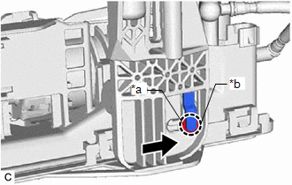
| *a | Protrusion |
| *b | Installation Hole |
.png) | Slide |
(9) Connect the 2 fuel pump harness connectors.
(10) Engage the clamp to connect the fuel pump harness to the fuel suction plate sub-assembly.
NOTICE:
- Do not damage the wire harness.
- When engaging each wire harness to the clamp, engage one wire at a time.
(b) for Type B:
| (1) Apply gasoline to a new O-ring. Then install the O-ring and fuel pump spacer to the fuel pump. |
|
(2) Install the fuel pump to the fuel tube supporter.
(3) Engage the 3 claws to install the No. 2 fuel suction support to the fuel tube supporter.
(4) Connect the fuel pump harness connector.
| (5) Engage the claw to connect the fuel pump harness. NOTICE:
|
|
.png)
(6) Check the connection state of the fuel pump harness.
Measure the resistance according to the value(s) in the table below.
Standard Resistance:
| Tester Connection | Condition | Specified Condition |
|---|---|---|
| Fuel pump body - Ground terminal of the fuel pump harness | Always | Below 50 Ω |
If the result is not as specified, reconnect the fuel pump harness to the fuel pump so that the ground terminal of the fuel pump harness is securely connected to the fuel pump body.
(7) Engage the 4 claws to install the fuel suction plate sub-assembly to the fuel sub-tank sub-assembly.
(8) Align the protrusion of the fuel sub-tank sub-assembly with the installation hole of the fuel suction plate sub-assembly and then slide the fuel suction plate sub-assembly to install the fuel sub-tank sub-assembly.
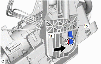
| *a | Protrusion |
| *b | Installation Hole |
| | Slide |
(9) Connect the 2 fuel pump harness connectors.
(10) Engage the clamp to connect the fuel pump harness to the fuel suction plate sub-assembly.
NOTICE:
- Do not damage the wire harness.
- When engaging each wire harness to the clamp, engage one wire at a time.
2. INSTALL FUEL SENDER GAUGE ASSEMBLY
Click here
READ NEXT:
 Installation
INSTALLATION PROCEDURE 1. INSTALL FUEL SUCTION TUBE WITH PUMP AND GAUGE ASSEMBLY (a) Install a new fuel suction tube set gasket to the fuel tank assembly. (b) Insert the fuel suction tube with pump
Components
COMPONENTS ILLUSTRATION *A for EGR Valve Bracket Connection Type *B for Cylinder Head Cover Sub-assembly Connection Type *1 FUEL PUMP ASSEMBLY *2 NO. 1 FUEL PIPE SUB-ASSEMBLY *
SEE MORE:
Installation
INSTALLATION PROCEDURE 1. INSTALL CLEARANCE WARNING ECU ASSEMBLY (a) Engage the claw to install the clearance warning ECU assembly as shown in the illustration. Install in this Direction 2. INSTALL ECU INTEGRATION BOX RH Click here 3. INSTALL GLOVE COMPARTMENT DOOR ASSEMBLY Click here
HV Control System Regenerative Malfunction (C1259,C1310)
DESCRIPTION The skid control ECU (brake booster with master cylinder assembly) communicates with the hybrid vehicle control ECU and controls braking force according to the motor's regenerative force. The skid control ECU (brake booster with master cylinder assembly) sends enhanced-VSC signals to the
