Lexus ES: Short to +B in Outer Mirror Indicator(Master) (C1AB0)
DESCRIPTION
This DTC is stored when the blind spot monitor sensor RH detects a short to +B in the outer rear view mirror indicator RH.
| DTC No. | Detection Item | DTC Detection Condition | Trouble Area |
|---|---|---|---|
| C1AB0 | Short to +B in Outer Mirror Indicator(Master) | Both of the following conditions are met:
|
|
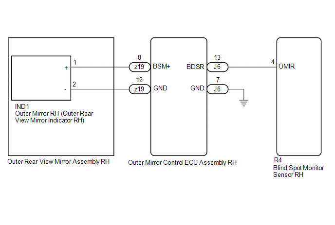
WIRING DIAGRAM
CAUTION / NOTICE / HINT
NOTICE:
When checking for DTCs, make sure that the blind spot monitor system is turned on.
PROCEDURE
| 1. | CHECK DTC |
(a) Turn the engine switch off.
(b) Turn the engine switch on (IG).
(c) Recheck for DTCs and check if the same DTC is output again.
Body Electrical > Blind Spot Monitor Master > Trouble CodesOK:
No DTCs are output.
| OK |  | USE SIMULATION METHOD TO CHECK |
|

| 2. | CHECK HARNESS AND CONNECTOR (OUTER REAR VIEW MIRROR INDICATOR CIRCUIT) |
(a) Disconnect the R4 blind spot monitor sensor RH connector.
(b) Measure the voltage according to the value(s) in the table below.
Standard Voltage:
| Tester Connection | Condition | Specified Condition |
|---|---|---|
| R4-4 (OMIR) - Body ground | Engine switch on (IG) | Below 1 V |
| OK | | REPLACE BLIND SPOT MONITOR SENSOR RH |
.gif)
|
| 3. | CHECK HARNESS AND CONNECTOR (OUTER REAR VIEW MIRROR INDICATOR CIRCUIT) |
(a) Disconnect the IND1 outer mirror RH connector.
(b) Measure the voltage according to the value(s) in the table below.
Standard Voltage:
| Tester Connection | Condition | Specified Condition |
|---|---|---|
| R4-4 (OMIR) - Body ground | Engine switch on (IG) | Below 1 V |
| OK | | REPLACE OUTER MIRROR RH |
|
| 4. | CHECK HARNESS AND CONNECTOR (OUTER REAR VIEW MIRROR INDICATOR CIRCUIT) |
(a) Disconnect the z19 outer rear view mirror assembly RH connector.
(b) Measure the voltage according to the value(s) in the table below.
Standard Voltage:
| Tester Connection | Condition | Specified Condition |
|---|---|---|
| R4-4 (OMIR) - Body ground | Engine switch on (IG) | Below 1 V |
| OK | | REPLACE OUTER REAR VIEW MIRROR ASSEMBLY RH |
|
| 5. | CHECK HARNESS AND CONNECTOR (OUTER REAR VIEW MIRROR INDICATOR CIRCUIT) |
(a) Disconnect the J6 outer mirror control ECU assembly RH connector.
(b) Measure the voltage according to the value(s) in the table below.
Standard Voltage:
| Tester Connection | Condition | Specified Condition |
|---|---|---|
| R4-4 (OMIR) - Body ground | Engine switch on (IG) | Below 1 V |
| OK | | REPLACE OUTER MIRROR CONTROL ECU ASSEMBLY RH |
| NG | | REPAIR OR REPLACE HARNESS OR CONNECTOR |
READ NEXT:
 Short to +B in Outer Mirror Indicator(Slave) (C1AB1)
DESCRIPTION This DTC is stored when the blind spot monitor sensor LH detects a short to +B in the outer rear view mirror indicator LH. DTC No. Detection Item DTC Detection Condition Trouble A
Short to GND in Outer Mirror Indicator(Master) (C1AB2)
DESCRIPTION This DTC is stored when the blind spot monitor sensor RH detects a short to ground in the outer rear view mirror indicator RH. DTC No. Detection Item DTC Detection Condition Troub
Short to GND in Outer Mirror Indicator(Slave) (C1AB3)
DESCRIPTION This DTC is stored when the blind spot monitor sensor LH detects a short to ground in the outer rear view mirror indicator LH. DTC No. Detection Item DTC Detection Condition Troub
SEE MORE:
Components
COMPONENTS ILLUSTRATION *1 CLEARANCE WARNING ECU ASSEMBLY *2 ECU INTEGRATION BOX RH *3 GLOVE COMPARTMENT DOOR ASSEMBLY - -
Fuel Rail Pressure Sensor (Low) Circuit Short to Ground (P107A11)
DESCRIPTION The No. 2 fuel pressure sensor (for low pressure side) replaces the fuel pressure with electrical signals and outputs them to the ECM. The ECM controls the optimal fuel pressure for the operation conditions to reduce the fuel pump power consumption and improve fuel economy. DTC No.
