Lexus ES: Short to GND in Outer Mirror Indicator(Slave) (C1AB3)
DESCRIPTION
This DTC is stored when the blind spot monitor sensor LH detects a short to ground in the outer rear view mirror indicator LH.
| DTC No. | Detection Item | DTC Detection Condition | Trouble Area |
|---|---|---|---|
| C1AB3 | Short to GND in Outer Mirror Indicator(Slave) | Both of the following conditions are met:
|
|
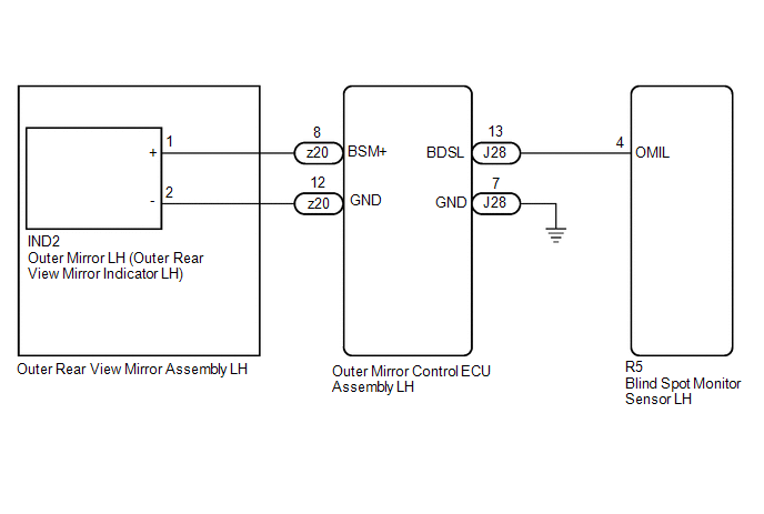
WIRING DIAGRAM
CAUTION / NOTICE / HINT
NOTICE:
When checking for DTCs, make sure that the blind spot monitor system is turned on.
PROCEDURE
| 1. | CHECK DTC |
(a) Turn the engine switch off.
(b) Turn the engine switch on (IG).
(c) Recheck for DTCs and check if the same DTC is output again.
Body Electrical > Blind Spot Monitor Slave > Trouble CodesOK:
No DTCs are output.
| OK |  | USE SIMULATION METHOD TO CHECK |
|

| 2. | CHECK HARNESS AND CONNECTOR (BLIND SPOT MONITOR SENSOR LH - OUTER MIRROR CONTROL ECU ASSEMBLY LH) |
(a) Disconnect the R5 blind spot monitor sensor LH connector.
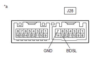
(b) Disconnect the J28 outer mirror control ECU assembly LH connector.
(c) Measure the resistance according to the value(s) in the table below.
Standard Resistance:
| Tester Connection | Condition | Specified Condition |
|---|---|---|
| R5-4 (OMIL) - Body ground | Always | 10 kΩ or higher |
| NG | | REPAIR OR REPLACE HARNESS OR CONNECTOR |
|
| 3. | INSPECT OUTER REAR VIEW MIRROR ASSEMBLY LH |
(a) Disconnect the z20 outer rear view mirror assembly LH connector.
(b) Disconnect the IND2 outer mirror LH connector.
(c) Measure the resistance according to the value(s) in the table below.
Standard Resistance:
| Tester Connection | Condition | Specified Condition |
|---|---|---|
| z20-8 (BSM+) - Body ground | Always | 10 kΩ or higher |
| NG | | REPLACE OUTER REAR VIEW MIRROR ASSEMBLY LH |
|
| 4. | INSPECT OUTER MIRROR CONTROL ECU ASSEMBLY LH |
| (a) Measure the resistance according to the value(s) in the table below. Standard Resistance:
|
|
| NG | | REPLACE OUTER MIRROR CONTROL ECU ASSEMBLY LH |
|
| 5. | INSPECT OUTER MIRROR LH |
(a) Remove the outer mirror LH.
Click here .gif)
(b) Inspect the outer rear view mirror indicator LH on the outer mirror LH.
Click here
| OK | | REPLACE BLIND SPOT MONITOR SENSOR LH |
| NG | | REPLACE OUTER MIRROR LH |
READ NEXT:
 Open in Outer Mirror Indicator(Master) (C1AB4)
DESCRIPTION This DTC is stored when the blind spot monitor sensor RH detects an open in the outer rear view mirror indicator RH. DTC No. Detection Item DTC Detection Condition Trouble Area
Open in Outer Mirror Indicator(Slave) (C1AB5)
DESCRIPTION This DTC is stored when the blind spot monitor sensor LH detects an open in the outer rear view mirror indicator LH. DTC No. Detection Item DTC Detection Condition Trouble Area
Blind Spot Monitor Master Module (C1AB6)
DESCRIPTION This DTC is stored when the blind spot monitor sensor RH detects an internal malfunction. DTC No. Detection Item DTC Detection Condition Trouble Area C1AB6 Blind Spot Monito
SEE MORE:
Window Glass Antenna Wire
On-vehicle InspectionON-VEHICLE INSPECTION PROCEDURE 1. INSPECT WINDOW GLASS ANTENNA WIRE (a) Check the continuity of the antenna. HINT: Check for continuity at the center of each antenna wire as shown in the illustration. NOTICE:
When cleaning the glass, wipe it in the direction of the wir
Engine Failed to Start Mechanical Linkage Failure (P1C7779)
DTC SUMMARY MALFUNCTION DESCRIPTION This DTC is stored when the hybrid vehicle control ECU determines that the hybrid vehicle transaxle assembly has seized or that there is the hybrid vehicle transaxle assembly malfunction in the drivetrain. The cause of this malfunction may be one of the following:
