Lexus ES: Short to +B in Outer Mirror Indicator(Slave) (C1AB1)
DESCRIPTION
This DTC is stored when the blind spot monitor sensor LH detects a short to +B in the outer rear view mirror indicator LH.
| DTC No. | Detection Item | DTC Detection Condition | Trouble Area |
|---|---|---|---|
| C1AB1 | Short to +B in Outer Mirror Indicator(Slave) | Both of the following conditions are met:
|
|
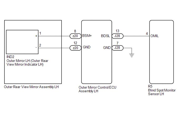
WIRING DIAGRAM
CAUTION / NOTICE / HINT
NOTICE:
When checking for DTCs, make sure that the blind spot monitor system is turned on.
PROCEDURE
| 1. | CHECK DTC |
(a) Turn the engine switch off.
(b) Turn the engine switch on (IG).
(c) Recheck for DTCs and check if the same DTC is output again.
Body Electrical > Blind Spot Monitor Slave > Trouble CodesOK:
No DTCs are output.
| OK |  | USE SIMULATION METHOD TO CHECK |
|

| 2. | CHECK HARNESS AND CONNECTOR (OUTER REAR VIEW MIRROR INDICATOR CIRCUIT) |
(a) Disconnect the R5 blind spot monitor sensor LH connector.
(b) Measure the voltage according to the value(s) in the table below.
Standard Voltage:
| Tester Connection | Condition | Specified Condition |
|---|---|---|
| R5-4 (OMIL) - Body ground | Engine switch on (IG) | Below 1 V |
| OK | | REPLACE BLIND SPOT MONITOR SENSOR LH |
.gif)
|
| 3. | CHECK HARNESS AND CONNECTOR (OUTER REAR VIEW MIRROR INDICATOR CIRCUIT) |
(a) Disconnect the IND2 outer mirror LH connector.
(b) Measure the voltage according to the value(s) in the table below.
Standard Voltage:
| Tester Connection | Condition | Specified Condition |
|---|---|---|
| R5-4 (OMIL) - Body ground | Engine switch on (IG) | Below 1 V |
| OK | | REPLACE OUTER MIRROR LH |
|
| 4. | CHECK HARNESS AND CONNECTOR (OUTER REAR VIEW MIRROR INDICATOR CIRCUIT) |
(a) Disconnect the z20 outer rear view mirror assembly LH connector.
(b) Measure the voltage according to the value(s) in the table below.
Standard Voltage:
| Tester Connection | Condition | Specified Condition |
|---|---|---|
| R5-4 (OMIL) - Body ground | Engine switch on (IG) | Below 1 V |
| OK | | REPLACE OUTER REAR VIEW MIRROR ASSEMBLY LH |
|
| 5. | CHECK HARNESS AND CONNECTOR (OUTER REAR VIEW MIRROR INDICATOR CIRCUIT) |
(a) Disconnect the J28 outer mirror control ECU assembly LH connector.
(b) Measure the voltage according to the value(s) in the table below.
Standard Voltage:
| Tester Connection | Condition | Specified Condition |
|---|---|---|
| R5-4 (OMIL) - Body ground | Engine switch on (IG) | Below 1 V |
| OK | | REPLACE OUTER MIRROR CONTROL ECU ASSEMBLY LH |
| NG | | REPAIR OR REPLACE HARNESS OR CONNECTOR |
READ NEXT:
 Short to GND in Outer Mirror Indicator(Master) (C1AB2)
DESCRIPTION This DTC is stored when the blind spot monitor sensor RH detects a short to ground in the outer rear view mirror indicator RH. DTC No. Detection Item DTC Detection Condition Troub
Short to GND in Outer Mirror Indicator(Slave) (C1AB3)
DESCRIPTION This DTC is stored when the blind spot monitor sensor LH detects a short to ground in the outer rear view mirror indicator LH. DTC No. Detection Item DTC Detection Condition Troub
Open in Outer Mirror Indicator(Master) (C1AB4)
DESCRIPTION This DTC is stored when the blind spot monitor sensor RH detects an open in the outer rear view mirror indicator RH. DTC No. Detection Item DTC Detection Condition Trouble Area
SEE MORE:
A/F (O2) Sensor Correlation Bank 1 Sensor 1/Bank 1 Sensor 2 Signal Compare Failure (P00D562)
DESCRIPTION Refer to DTC P003012. Click here Refer to DTC P003612. Click here HINT: Although the DTC title say O2 sensor, this DTC relate to the air fuel ratio sensors (sensor 1 and sensor 2). DTC No. Detection Item DTC Detection Condition Trouble Area MIL Memory Note P00D562
Reverse Shift-linked Function of Power Mirrors does not Operate
DESCRIPTION The ECM sends the reverse signal to the main body ECU (multiplex network body ECU) via CAN communication. When receiving the reverse signal, the main body ECU (multiplex network body ECU) sends the reverse request signal to each outer mirror control ECU assembly. Based on the signal, eac
