Lexus ES: Shift Paddle Switch Circuit
DESCRIPTION
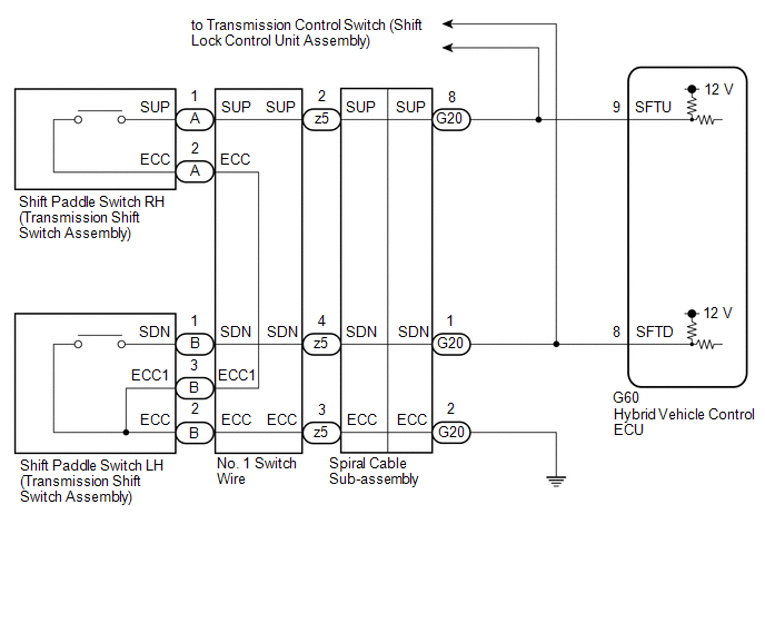
Moving the shift lever to S enables the shift range to be selected. The shift range can be selected by operating the "+" or "-" shift paddle switch.
WIRING DIAGRAM
CAUTION / NOTICE / HINT
NOTICE:
After turning the power switch off, waiting time may be required before disconnecting the cable from the negative (-) auxiliary battery terminal. Therefore, make sure to read the disconnecting the cable from the negative (-) auxiliary battery terminal notices before proceeding with work.
Click here .gif)
PROCEDURE
| 1. | READ VALUE USING TECHSTREAM (SPORTS SHIFT UP SIGNAL, SPORTS SHIFT DOWN SIGNAL) |
(a) Connect the Techstream to the DLC3.
(b) Turn the power switch on (IG).
(c) Enter the following menus: Powertrain / Hybrid Control / Data List / Sports Shift UP Signal, Sports Shift DOWN Signal.
Powertrain > Hybrid Control > Data List| Tester Display |
|---|
| Sports Shift UP Signal |
| Sports Shift DOWN Signal |
(d) Read the values displayed on the Techstream.
| Result | Proceed to |
|---|---|
| The Techstream display changes according to the shift paddle switch (transmission shift switch assembly) operation | A |
| The Techstream display does not change according to the shift paddle switch (transmission shift switch assembly) operation | B |
(e) Turn the power switch off.
| A | .gif) | CHECK FOR INTERMITTENT PROBLEMS |
|
.gif)
| 2. | CHECK HARNESS AND CONNECTOR (SHIFT PADDLE SWITCH CIRCUIT) |
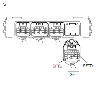
(a) Disconnect the G60 hybrid vehicle control ECU connector.
(b) Disconnect the G26 transmission control switch (shift lock control unit assembly) connector.
| (c) Measure the resistance according to the value(s) in the table below. Standard Resistance:
|
|
(d) Reconnect the G26 transmission control switch (shift lock control unit assembly) connector.
(e) Reconnect the G60 hybrid vehicle control ECU connector.
| OK | | REPLACE HYBRID VEHICLE CONTROL ECU |
|
| 3. | CHECK HARNESS AND CONNECTOR (SPIRAL CABLE SUB-ASSEMBLY - BODY GROUND) |
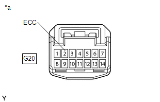
| (a) Disconnect the G20 spiral cable sub-assembly connector. |
|
(b) Measure the resistance according to the value(s) in the table below.
Standard Resistance (Open):
| Tester Connection | Condition | Specified Condition |
|---|---|---|
| G20-2 (ECC) - Body ground | Always | Below 1 Ω |
(c) Reconnect the G20 spiral cable sub-assembly connector.
| NG | | REPAIR OR REPLACE HARNESS OR CONNECTOR |
|
| 4. | CHECK HARNESS AND CONNECTOR (SPIRAL CABLE SUB-ASSEMBLY - HYBRID VEHICLE CONTROL ECU) |
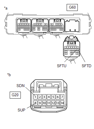
(a) Disconnect the G60 hybrid vehicle control ECU connector.
(b) Disconnect the G20 spiral cable sub-assembly connector.
| (c) Measure the resistance according to the value(s) in the table below. Standard Resistance:
|
|
(d) Reconnect the G20 spiral cable sub-assembly connector.
(e) Reconnect the G60 hybrid vehicle control ECU connector.
| NG | | REPAIR OR REPLACE HARNESS OR CONNECTOR |
|
| 5. | INSPECT SPIRAL CABLE SUB-ASSEMBLY |
(a) Inspect the spiral cable sub-assembly.
Click here
| NG | | REPLACE SPIRAL CABLE SUB-ASSEMBLY |
|
| 6. | INSPECT SHIFT PADDLE SWITCH LH (TRANSMISSION SHIFT SWITCH ASSEMBLY) |
(a) Inspect the shift paddle switch LH (transmission shift switch assembly).
Click here
| NG | | REPLACE SHIFT PADDLE SWITCH LH (TRANSMISSION SHIFT SWITCH ASSEMBLY) |
|
| 7. | INSPECT SHIFT PADDLE SWITCH RH (TRANSMISSION SHIFT SWITCH ASSEMBLY) |
(a) Inspect the shift paddle switch RH (transmission shift switch assembly).
Click here
| NG | | REPLACE SHIFT PADDLE SWITCH RH (TRANSMISSION SHIFT SWITCH ASSEMBLY) |
|
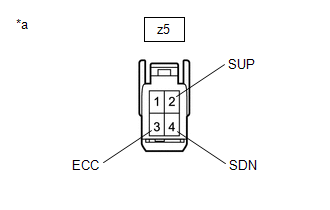
| 8. | INSPECT NO. 1 SWITCH WIRE |
(a) Disconnect the z5 No. 1 switch wire connector.
| (b) Measure the resistance according to the value(s) in the table below. Standard Resistance:
|
|
(c) Reconnect the z5 No. 1 switch wire connector.
| OK | | CHECK FOR INTERMITTENT PROBLEMS |
| NG | | REPLACE NO. 1 SWITCH WIRE |
READ NEXT:
 Pattern Select Switch EV Mode Circuit
DESCRIPTION The EV drive mode signal will be sent to the hybrid vehicle control ECU when the EV drive mode switch (NO. 3 combination switch assembly) is operated. If the specified conditions are met,
Pattern Select Switch Sport Mode Circuit
DESCRIPTION When selecting sport mode, the switch operation signal is sent to the hybrid vehicle control ECU. Following this, the system enters sport mode and the vehicle will be driven using sport mo
Pattern Select Switch Eco Mode Circuit
DESCRIPTION When selecting Eco drive mode, the drive mode select switch (combination switch assembly) (Eco drive mode) operation signal is sent to the air conditioning amplifier assembly. Following th
SEE MORE:
Components
COMPONENTS ILLUSTRATION *1 FUEL DELIVERY PIPE *2 FUEL INJECTOR SEAL *3 DIRECT FUEL INJECTOR ASSEMBLY *4 SENSOR WIRE *5 NO. 3 FUEL INJECTOR BACK-UP RING *6 O-RING *7 NO. 1 FUEL INJECTOR BACK-UP RING *8 NOZZLE HOLDER CLAMP *9 INJECTOR VIBRATION INSULATOR
Installation
INSTALLATION PROCEDURE 1. INSTALL NO. 2 RADIO BRACKET HINT: Perform this procedure only when replacement of the No. 2 radio bracket is necessary. (a) Install the No. 2 radio bracket with the 3 screws. 2. INSTALL NO. 1 RADIO BRACKET HINT: Perform this procedure only when replacement of the No. 1 radi
