Lexus ES: Parts Location
Lexus ES (XZ10) Service Manual / Vehicle Exterior / Window / Glass / Window Defogger System (for Gasoline Model) / Parts Location
PARTS LOCATION
ILLUSTRATION
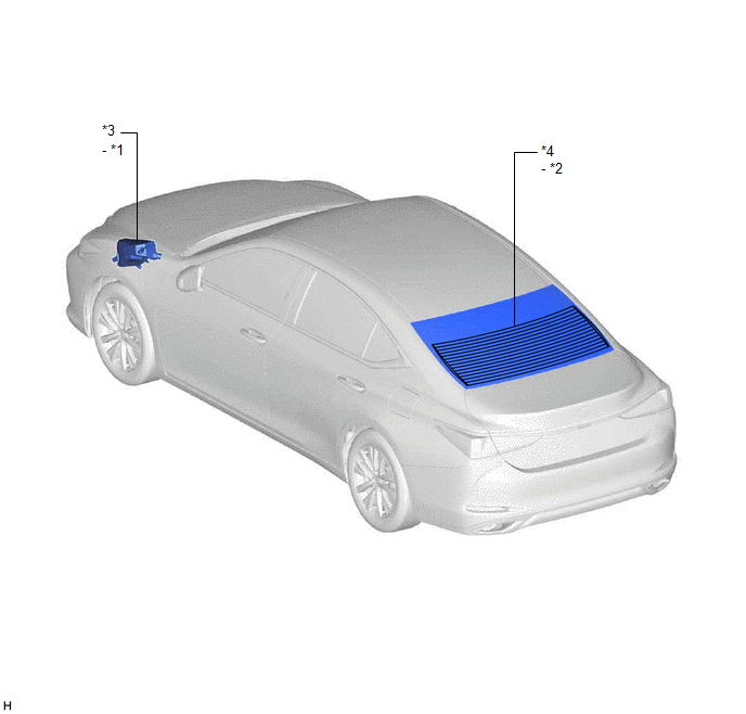
| *1 | DEF RELAY | *2 | REAR WINDOW DEFOGGER WIRE |
| *3 | NO. 1 ENGINE ROOM RELAY BLOCK AND NO. 1 JUNCTION BLOCK ASSEMBLY - DEF FUSE | *4 | BACK WINDOW GLASS |
ILLUSTRATION

| *1 | REAR WINDOW DEFOGGER SWITCH (AIR CONDITIONING CONTROL ASSEMBLY) | *2 | DLC3 |
| *3 | AIR CONDITIONING AMPLIFIER ASSEMBLY | *4 | INSTRUMENT PANEL JUNCTION BLOCK ASSEMBLY - ECU-IG1 NO. 3 FUSE |
READ NEXT:
 System Diagram
SYSTEM DIAGRAM Communication Table Transmitter Receiver Signal Communication Method Rear Window Defogger Switch (Air Conditioning Control Assembly) Air Conditioning Amplifier Assembly
System Description
SYSTEM DESCRIPTION GENERAL (a) The rear window defogger wire (back window glass) is attached to the inside of the rear window and defogs the window surface quickly when the rear window defogger switch
How To Proceed With Troubleshooting
CAUTION / NOTICE / HINT HINT:
Use the following procedure to troubleshoot the window defogger system.
*: Use the Techstream.
PROCEDURE 1. VEHICLE BROUGHT TO WORKSHOP
NEXT
SEE MORE:
Installation
INSTALLATION PROCEDURE 1. INSTALL ACTIVE NOISE CONTROL MICROPHONE (for Front Side) HINT:
Use the same procedure for the RH side and LH side.
The following procedure is for the LH side.
(a) Connect the connector. Install in this Direction (b) Engage the 2 claws to install the active
Switch Lights of Remote Touch do not Illuminate
DESCRIPTION Power is supplied to the remote touch (remote operation controller assembly) illumination when the light control switch is in the tail or head position. WIRING DIAGRAM CAUTION / NOTICE / HINT NOTICE: Inspect the fuse for circuits related to this system before performing the following pr
© 2016-2026 Copyright www.lexguide.net
