Lexus ES: Pattern Select Switch Eco Mode Circuit
DESCRIPTION
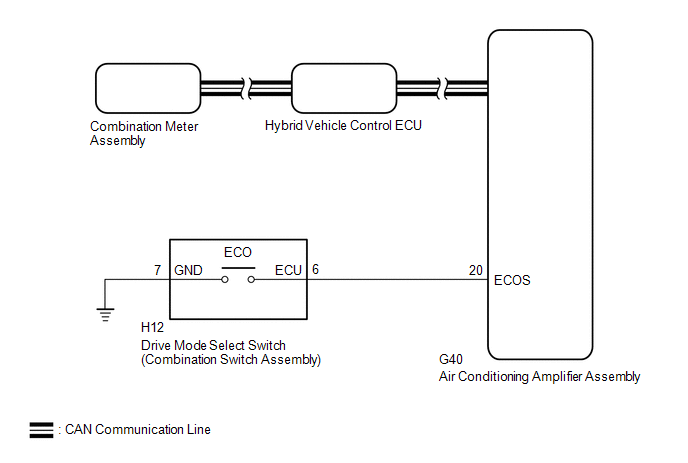
When selecting Eco drive mode, the drive mode select switch (combination switch assembly) (Eco drive mode) operation signal is sent to the air conditioning amplifier assembly. Following this, Eco drive mode control is activated for the heater and air conditioning system and the hybrid vehicle control system.
WIRING DIAGRAM
PROCEDURE
| 1. | READ VALUE USING TECHSTREAM (CAN BUS CHECK) |
Click here .gif)
| Result | Proceed to |
|---|---|
| All of the ECUs and sensors that are currently connected to the CAN communication system are displayed | A |
| None of the ECUs and sensors that are currently connected to the CAN communication system are displayed, or some of them are not displayed | B |
| B | .gif) | GO TO CAN COMMUNICATION SYSTEM |
|
.gif)
| 2. | CHECK DTC OUTPUT (HEALTH CHECK) |
Click here
| Result | Proceed to |
|---|---|
| No DTCs are output | A |
| DTCs are output | B |
| B | | GO TO DTC CHART |
|
| 3. | READ VALUE USING TECHSTREAM (ECO SWITCH) |
(a) Connect the Techstream to the DLC3.
(b) Turn the power switch on (IG).
(c) Enter the following menus: Body Electrical / Air Conditioner / Data List / ECO Switch.
Body Electrical > Air Conditioner > Data List| Tester Display |
|---|
| ECO Switch |
(d) Read the value displayed on the Techstream.
| Result | Proceed to |
|---|---|
| The Techstream display changes according to the drive mode select switch (combination switch assembly) operation | A |
| The Techstream display does not change according to the drive mode select switch (combination switch assembly) operation | B |
| A | | CHECK FOR INTERMITTENT PROBLEMS |
|
| 4. | INSPECT DRIVE MODE SELECT SWITCH (COMBINATION SWITCH ASSEMBLY) (ECO DRIVE MODE) |
Click here
| NG | | REPLACE DRIVE MODE SELECT SWITCH (COMBINATION SWITCH ASSEMBLY) |
|
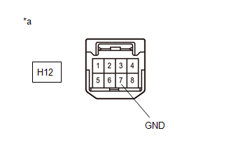
| 5. | CHECK HARNESS AND CONNECTOR (DRIVE MODE SELECT SWITCH (COMBINATION SWITCH ASSEMBLY) - BODY GROUND) |
(a) Disconnect the H12 drive mode select switch (combination switch assembly) connector.
| (b) Measure the resistance according to the value(s) in the table below. Standard Resistance:
|
|
(c) Reconnect the H12 drive mode select switch (combination switch assembly) connector.
| NG | | REPAIR OR REPLACE HARNESS OR CONNECTOR |
|
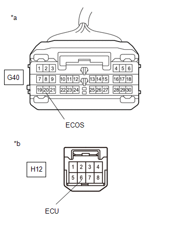
| 6. | CHECK HARNESS AND CONNECTOR (AIR CONDITIONING AMPLIFIER ASSEMBLY - DRIVE MODE SELECT SWITCH (COMBINATION SWITCH ASSEMBLY)) |
(a) Disconnect the G40 air conditioning amplifier assembly connector.
(b) Disconnect the H12 drive mode select switch (combination switch assembly) connector.
| (c) Measure the resistance according to the value(s) in the table below. Standard Resistance:
|
|
(d) Reconnect the H12 drive mode select switch (combination switch assembly) connector.
(e) Reconnect the G40 air conditioning amplifier assembly connector.
| OK | | REPLACE AIR CONDITIONING AMPLIFIER ASSEMBLY |
| NG | | REPAIR OR REPLACE HARNESS OR CONNECTOR |
READ NEXT:
 Indicator Circuit
DESCRIPTION In accordance with the shift lever position, each shift position indicator light will turn on. WIRING DIAGRAM PROCEDURE 1. CHECK SHIFT POSITION INDICATOR (a) Turn the power switc
Drive Start Control
DESCRIPTION The drive start control is controlled by the hybrid vehicle control ECU. If the hybrid vehicle control ECU determines that the shift lever and accelerator pedal are operated abnormally, hy
ECU Power Source Circuit
DESCRIPTION If the power switch is on (IG), the hybrid vehicle control ECU applies current to the MREL terminal to turn the IGCT relay on. This supplies power to the +B1 and +B2 terminals. WIRING DIAG
SEE MORE:
Installation
INSTALLATION CAUTION / NOTICE / HINT HINT:
Use the same procedure for the RH side and LH side.
The following procedure is for the LH side.
PROCEDURE 1. INSTALL OUTER REAR VIEW MIRROR ASSEMBLY (a) Engage the 2 guides and claw. (b) Install the outer rear view mirror assembly with the 3 nuts. T
ECM/PCM Power Relay Sense Circuit Intermittent (P06881F)
DESCRIPTION This DTC indicates that the hybrid vehicle control ECU detected an instantaneous interruption in +B power source voltage. DTC No. Detection Item DTC Detection Condition Trouble Area MIL Warning Indicate P06881F ECM/PCM Power Relay Sense Circuit Intermittent When the
