Lexus ES: Replacement
REPLACEMENT
CAUTION / NOTICE / HINT
The necessary procedures (adjustment, calibration, initialization, or registration) that must be performed after parts are removed and installed, or replaced during rear axle hub bolt removal/installation are shown below.
Necessary Procedures After Parts Removed/Installed/Replaced (for HV Model:)| Replaced Part or Performed Procedure | Necessary Procedure | Effect/Inoperative Function when Necessary Procedure not Performed | Link |
|---|---|---|---|
|
*: When performing learning using the Techstream.
Click here | |||
| Auxiliary battery terminal is disconnected/reconnected | Perform steering sensor zero point calibration | Lane Control System | |
| Pre-collision System | |||
| Parking Support Brake System* | |||
| Lighting System | |||
| Memorize steering angle neutral point | Parking Assist Monitor System | | |
| Panoramic View Monitor System | | ||
| Initialize power trunk lid system | Power Trunk Lid System (for HV Model) | | |
NOTICE:
for HV Model:- After the power switch is turned off, the radio receiver assembly records various types of memory and settings. As a result, after turning the power switch off, make sure to wait at least 85 seconds before disconnecting the cable from the negative (-) auxiliary battery terminal. (for Audio and Visual System)
- After the power switch is turned off, the radio receiver assembly records various types of memory and settings. As a result, after turning the power switch off, make sure to wait at least 85 seconds before disconnecting the cable from the negative (-) auxiliary battery terminal. (for Navigation System)
CAUTION / NOTICE / HINT
for HV Model:- When removing or installing the rear disc brake caliper assembly, pushing back the disc brake piston may cause a large clearance between the brake pads and brake disc. When the brake pedal is depressed with a large clearance between the brake pads and the brake disc, DTC C1214 related to abnormal brake fluid pressure may be stored. Make sure to clear any DTCs after performing this procedure.
- While the auxiliary battery is connected, even if the power switch is off, the brake control system activates when the brake pedal is depressed or any door courtesy switch turns on. Therefore, when servicing the brake system components, do not operate the brake pedal or open/close the doors while the auxiliary battery is connected.
HINT:
- Use the same procedure for the RH side and LH side.
- The following procedure is for the LH side.
PROCEDURE
1. PRECAUTION (for HV Model)
NOTICE:
After turning the power switch off, waiting time may be required before disconnecting the cable from the negative (-) auxiliary battery terminal. Therefore, make sure to read the disconnecting the cable from the negative (-) auxiliary battery terminal notices before proceeding with work.
2. DISABLE BRAKE CONTROL (for HV Model)
Click here .gif)
3. REMOVE REAR WHEEL
Click here
4. DISCONNECT NO. 2 PARKING BRAKE WIRE ASSEMBLY
Click here
5. SEPARATE REAR DISC BRAKE CALIPER ASSEMBLY
(a) Remove the 2 bolts and separate the rear disc brake caliper assembly from the rear axle carrier sub-assembly.
NOTICE:
Use wire or an equivalent tool to keep the rear disc brake caliper assembly from hanging by the rear flexible hose.
6. REMOVE REAR DISC
Click here
7. REMOVE REAR AXLE HUB BOLT
| (a) Temporarily install 2 service nuts to the rear axle hub bolts as shown in the illustration. Recommended Service Nut: Thread diameter: 12.0 mm (0.472 in.) Thread pitch: 1.5 mm (0.0591 in.) NOTICE: Install the service nuts to prevent damage to the rear axle hub bolts. |
|
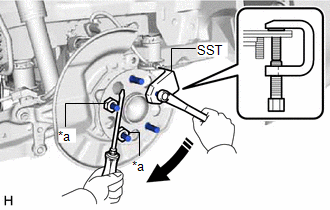
(b) Using SST and a screwdriver or an equivalent tool to hold the rear axle hub and bearing assembly, remove the rear axle hub bolt.
SST: 09628-10011
NOTICE:
Do not damage the threads of the rear axle hub bolts.
8. INSTALL REAR AXLE HUB BOLT
| (a) Temporarily install a new rear axle hub bolt to the rear axle hub and bearing assembly. |
|
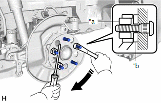
(b) Install a washer and service nut to the rear axle hub bolt as shown in the illustration.
Recommended Service Nut:
Thread diameter: 12.0 mm (0.472 in.)
Thread pitch: 1.5 mm (0.0591 in.)
HINT:
Recommended washer thickness is 5 mm (0.197 in.) or more.
(c) Using a screwdriver or an equivalent tool to hold the rear axle hub and bearing assembly, install the rear axle hub bolt by tightening the service nut.
NOTICE:
- Install the service nuts to prevent damage to the rear axle hub bolts.
- Do not damage the threads of the rear axle hub bolts.
(d) Remove the 3 service nuts and washer from the 3 rear axle hub bolts.
9. INSTALL REAR DISC
Click here
10. INSTALL REAR DISC BRAKE CALIPER ASSEMBLY
(a) Install the rear disc brake caliper assembly to the rear axle carrier sub-assembly with the 2 bolts.
Torque:
107 N·m {1091 kgf·cm, 79 ft·lbf}
11. CONNECT NO. 2 PARKING BRAKE WIRE ASSEMBLY
Click here
12. INSTALL REAR WHEEL
Click here
13. CONNECT CABLE TO NEGATIVE AUXILIARY BATTERY TERMINAL (for HV Model)
(a) Connect the reservoir level switch connector.
(b) Connect the cable to the negative (-) auxiliary battery terminal.
Click here
(c) Turn the power switch on (READY).
(d) Depress the brake pedal and release it.
(e) Clear the DTCs.
Click here
READ NEXT:
 Components
COMPONENTS ILLUSTRATION *1 REAR DIFFERENTIAL CARRIER ASSEMBLY *2 WIRE HARNESS CLAMP BRACKET *3 REAR UPPER DIFFERENTIAL MOUNT STOPPER *4 REAR LOWER DIFFERENTIAL MOUNT STOPPER *5
Disassembly
DISASSEMBLY CAUTION / NOTICE / HINT NOTICE: Before installation of each part, thoroughly clean and dry it. Then apply gear oil to it. Do not use alkaline chemicals to clean aluminum parts, rubber part
SEE MORE:
Starter Relay Circuit Short to Battery (P061512)
DESCRIPTION While the engine is being cranked, battery voltage is applied to terminal STA of the ECM. If the ECM detects the starter control (STA) signal while the vehicle is being driven, it determines that there is a malfunction in the STA circuit. The ECM then illuminates the MIL and stores this
System Description
SYSTEM DESCRIPTION DESCRIPTION
LEXUS ENFORM allows the vehicle to receive information from the call center and links the information to the audio and visual system*1 or navigation system*2. LEXUS ENFORM permits the driver to use the received information, such as destination information, on the au
