Lexus ES: Repair
REPAIR
CAUTION / NOTICE / HINT
HINT:
- Use the same procedure for the RH side and LH side.
- The following procedure is for the LH side.
- If the installation area of the headlight assembly is damaged, use a supply retainer for a low-cost repair.
- Ensure that the headlight assembly is not damaged.
PROCEDURE
1. INSTALL UPPER HEADLIGHT PROTECTOR RETAINER (for TMC Made)
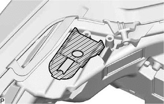
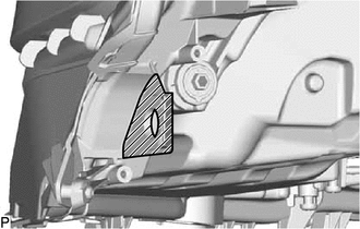
| (a) Cut off the part shaded in the illustration and sand smooth with sandpaper. HINT: After cutting off the part, place the upper headlight protector retainer against the bosses and gradually file away the old bracket if it interferes with the installation of a supply retainer. |
|
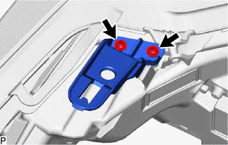
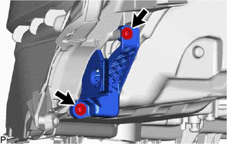
| (b) Install the upper headlight protector retainer with the 2 screws. |
|
2. INSTALL LOWER HEADLIGHT PROTECTOR RETAINER (for TMC Made)
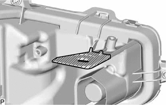
| (a) Cut off the part shaded in the illustration and sand smooth with sandpaper. HINT: After cutting off the part, place the lower headlight protector retainer against the bosses and gradually file away the old bracket if it interferes with the installation of a supply retainer. |
|
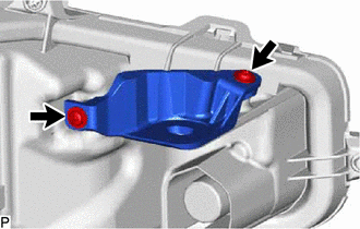
| (b) Install the lower headlight protector retainer with the 2 screws. |
|
3. INSTALL LOWER NO. 2 HEADLIGHT PROTECTOR RETAINER (for TMC Made)
| (a) Cut off the part shaded in the illustration and sand smooth with sandpaper. HINT: After cutting off the part, place the lower No. 2 headlight protector retainer against the bosses and gradually file away the old bracket if it interferes with the installation of a supply retainer. |
|
| (b) Install the lower No. 2 headlight protector retainer with the 2 screws. |
|
READ NEXT:
 Components
COMPONENTS ILLUSTRATION *1 LOWER STEERING COLUMN COVER SUB-ASSEMBLY *2 TURN SIGNAL SWITCH *3 UPPER STEERING COLUMN COVER - -
Removal
REMOVAL PROCEDURE 1. CHANGE POWER TILT AND POWER TELESCOPIC STEERING COLUMN SYSTEM SETTINGS (for Power Tilt and Power Telescopic Steering Column) Click here 2. REMOVE LOWER STEERING COLUMN COVER S
SEE MORE:
Brake Override System
DESCRIPTION When the vehicle is being driven with the accelerator pedal depressed, depressing the brake pedal without releasing the accelerator pedal will activate the brake override system to restrict hybrid system output. The conditions for activating the brake override system as well as the items
Position Initialization Incomplete (B2343)
DESCRIPTION This DTC is stored when the sliding roof ECU (sliding roof drive gear assembly) has not been initialized. DTC No. Detection Item DTC Detection Condition Trouble Area B2343 Position Initialization Incomplete Sliding roof ECU (sliding roof drive gear assembly) has not been
