Lexus ES: Components
Lexus ES (XZ10) Service Manual / Vehicle Interior / Lighting (ext) / Headlight Dimmer Switch / Components
COMPONENTS
ILLUSTRATION
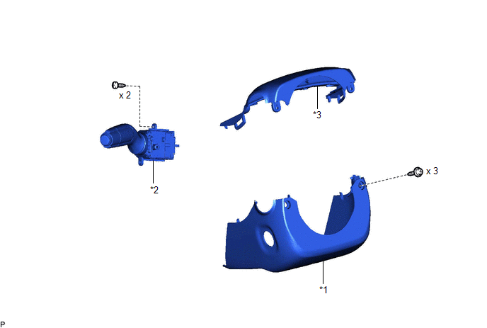
| *1 | LOWER STEERING COLUMN COVER SUB-ASSEMBLY | *2 | TURN SIGNAL SWITCH |
| *3 | UPPER STEERING COLUMN COVER | - | - |
READ NEXT:
 Removal
REMOVAL PROCEDURE 1. CHANGE POWER TILT AND POWER TELESCOPIC STEERING COLUMN SYSTEM SETTINGS (for Power Tilt and Power Telescopic Steering Column) Click here 2. REMOVE LOWER STEERING COLUMN COVER S
Inspection
INSPECTION PROCEDURE 1. INSPECT TURN SIGNAL SWITCH (a) Measure the resistance according to the value(s) in the table below. Standard Resistance: Light Control Switch Tester Connection Conditi
Installation
INSTALLATION PROCEDURE 1. INSTALL TURN SIGNAL SWITCH (a) Engage the claw as shown in the illustration. Install in this Direction (b) Install the turn signal switch with the 2 screws. 2. INST
SEE MORE:
Power Trunk Lid does not Operate Using Cabin Switch
DESCRIPTION The trunk and fuel switch assembly (luggage compartment door opening switch) signal is sent to the luggage closer motor assembly. If the power trunk lid does not operate using the trunk and fuel (luggage compartment door opening switch), a trunk and fuel (luggage compartment door opening
Fail-safe Chart
FAIL-SAFE CHART PROTECTION FUNCTION (a) The windshield wiper motor assembly operates the following protection functions if it detects an abnormal condition, in order to protect the wiper and washer system. Item Protection Content Conditions to Return to Normal Condition Overheat protectio
© 2016-2026 Copyright www.lexguide.net
