Lexus ES: Removal
REMOVAL
PROCEDURE
1. CHANGE POWER TILT AND POWER TELESCOPIC STEERING COLUMN SYSTEM SETTINGS (for Power Tilt and Power Telescopic Steering Column)
Click here .gif)
2. REMOVE LOWER STEERING COLUMN COVER SUB-ASSEMBLY
Click here
3. REMOVE UPPER STEERING COLUMN COVER
Click here
4. REMOVE TURN SIGNAL SWITCH
| (a) Remove the 2 screws. |
|
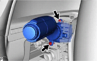
(b) Using a screwdriver with its tip wrapped with protective tape, disengage the claw and remove the turn signal switch as shown in the illustration.

| *a | Protective Tape |
.png) | Remove in this Direction |
NOTICE:
If the claw is pulled with excessive force, it may break.
READ NEXT:
 Inspection
INSPECTION PROCEDURE 1. INSPECT TURN SIGNAL SWITCH (a) Measure the resistance according to the value(s) in the table below. Standard Resistance: Light Control Switch Tester Connection Conditi
Installation
INSTALLATION PROCEDURE 1. INSTALL TURN SIGNAL SWITCH (a) Engage the claw as shown in the illustration. Install in this Direction (b) Install the turn signal switch with the 2 screws. 2. INST
SEE MORE:
Reassembly
REASSEMBLY CAUTION / NOTICE / HINT HINT:
Use the same procedure for bank 1 and bank 2.
The following procedure is for bank 2.
PROCEDURE 1. INSTALL SPARK PLUG TUBE HINT: When using a new cylinder head LH, the spark plug tubes must be replaced. (a) Apply adhesive to a new spark plug tube as
Removal
REMOVAL CAUTION / NOTICE / HINT The necessary procedures (adjustment, calibration, initialization or registration) that must be performed after parts are removed and installed, or replaced during fuel sender gauge assembly removal/installation are shown below. Necessary Procedures After Parts Remove
© 2016-2026 Copyright www.lexguide.net
