Lexus ES: Terminals Of Ecu
TERMINALS OF ECU
CHECK VEHICLE APPROACHING SPEAKER CONTROLLER

(a) Disconnect the G42 vehicle approaching speaker controller connector.
(b) Measure the voltage and resistance according to the value(s) in the table below.
| Terminal No. (Symbol) | Wiring Color | Terminal Description | Condition | Specified Condition |
|---|---|---|---|---|
| G42-1 (IG) - Body ground | LA-B - Body ground | IG power supply | Power switch on (IG) | 11 to 14 V |
| Power switch off | Below 1 V | |||
| G42-6 (GND) - Body ground | W-B - Body ground | Ground | Always | Below 1 Ω |
(c) Connect the G42 vehicle approaching speaker controller connector.
(d) Measure the check for pulses according to the value(s) in the table below.
| Terminal No. (Symbol) | Wiring Color | Terminal Description | Condition | Specified Condition |
|---|---|---|---|---|
| G42-7 (SP+) - G42-8 (SP-) | B - W | Vehicle approaching speaker output | Vehicle approaching speaker operating | A waveform synchronized with the sound is output. (See Waveform 1) |
| G42-3 (CANH) - G42-6 (GND) | B - W-B | CAN communication line | Power switch on (IG) | Pulse generation |
| G42-4 (CANL) - G42-6 (GND) | W - W-B | CAN communication line | Power switch on (IG) | Pulse generation |
(1) Waveform 1
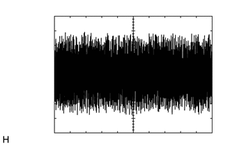
| Item | Condition |
|---|---|
| Tester Connection | G42-7 (SP+) - G42-8 (SP-) |
| Tool Setting | 1 V/DIV., 500 ms./DIV. |
| Condition | Vehicle approaching speaker operating |
READ NEXT:
 Dtc Check / Clear
DTC CHECK / CLEAR DTC CHECK (a) Connect the Techstream to the DLC3. (b) Turn the power switch on (IG). (c) Turn the Techstream on. (d) Enter the following menus: Body Electrical / Vehicle Proximity No
Data List / Active Test
DATA LIST / ACTIVE TEST DATA LIST NOTICE: In the table below, the values listed under "Normal Condition" are reference values. Do not depend solely on these reference values when deciding whether a pa
Diagnostic Trouble Code Chart
DIAGNOSTIC TROUBLE CODE CHART Vehicle Proximity Notification System DTC No. Detection Item Link B1350 Speaker Circuit U0129 Lost Communication with Brake System Control Module
SEE MORE:
Door Mirror ECU LH Communication Stop Mode
DESCRIPTION Detection Item Symptom Trouble Area Door Mirror ECU LH Communication Stop Mode Any of the following conditions are met:
Communication stop for "Front Door LH/L-Mirror (FL-Door/L-Mirror)" is indicated on the "Communication Bus Check" screen of the Techstream.
Click here
Diagnostic Trouble Code Chart
DIAGNOSTIC TROUBLE CODE CHART Panoramic View Monitor System DTC No. Detection Item DTC Detection Condition Link C1611 ECU Malfunction When any of the following conditions is met:
EEPROM status (Initial read) malfunction
CPU communication malfunction
Video output malfunction
