Lexus ES: Removal
REMOVAL
CAUTION / NOTICE / HINT
HINT:
- Use the same procedure for the RH side and LH side.
- The following procedure is for the LH side.
PROCEDURE
1. REMOVE NO. 2 ROCKER PANEL MOULDING PROTECTOR
Click here .gif)
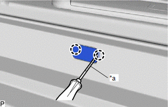
2. REMOVE ROCKER PANEL MOULDING COVER
| (a) Using a screwdriver with its tip wrapped with protective tape, disengage the 2 claws to remove the rocker panel moulding cover. HINT: Use the same procedure for the other rocker panel moulding cover. |
|
3. REMOVE BODY ROCKER PANEL MOULDING ASSEMBLY
(a) Apply protective tape around the body rocker panel moulding assembly and doors as shown in the illustration.
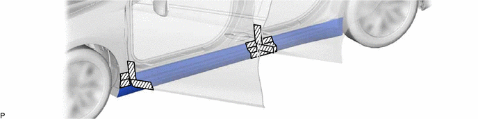
.png) | Protective Tape | - | - |
(b) Remove the 9 clips.
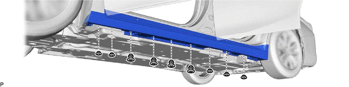
(c) Remove the 6 screws.
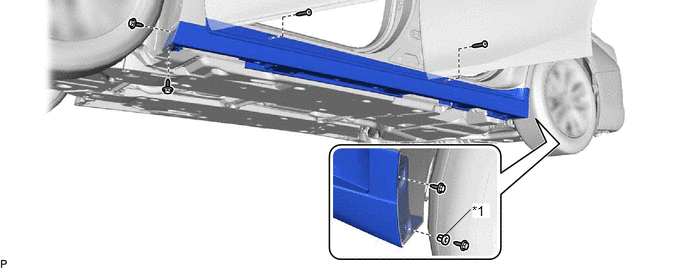
| *1 | Grommet | - | - |
(d) Remove the grommet
(e) Disengage the 9 clips to remove the body rocker panel moulding assembly as shown in the illustration.
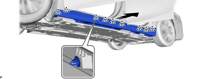
.png) | Remove in this Direction | - | - |
READ NEXT:
 Disassembly
DISASSEMBLY PROCEDURE 1. REMOVE NO. 4 ROCKER PANEL MOULDING PROTECTOR (a) Remove the No. 4 rocker panel moulding protector. 2. REMOVE NO. 5 ROCKER PANEL MOULDING PROTECTOR (a) Remove
Reassembly
REASSEMBLY PROCEDURE 1. INSTALL NO. 5 ROCKER PANEL MOULDING PROTECTOR HINT: When installing the No. 5 rocker panel moulding protector, heat the body rocker panel moulding assembly using a heat light.
Installation
INSTALLATION CAUTION / NOTICE / HINT HINT:
Use the same procedure for the RH side and LH side.
The following procedure is for the LH side.
PROCEDURE 1. INSTALL BODY ROCKER PANEL MOULDING ASSEM
SEE MORE:
Stereo Jack Adapter Light does not Illuminate
DESCRIPTION Power is supplied to the No. 1 stereo jack adapter assembly illumination from the radio receiver assembly. WIRING DIAGRAM CAUTION / NOTICE / HINT NOTICE:
Depending on the parts that are replaced during vehicle inspection or maintenance, performing initialization, registration or cali
Installation
INSTALLATION PROCEDURE 1. INSTALL SUSPENSION TOWER DAMPER (a) Install the suspension tower damper to the front bumper extension sub-assembly LH and front bumper extension sub-assembly RH with the 4 bolts. Torque: 27.5 N·m {280 kgf·cm, 20 ft·lbf} NOTICE: Do not extend or compress the damper. 2. I
© 2016-2026 Copyright www.lexguide.net
