Lexus ES: Reassembly
REASSEMBLY
PROCEDURE
1. INSTALL NO. 5 ROCKER PANEL MOULDING PROTECTOR
HINT:
When installing the No. 5 rocker panel moulding protector, heat the body rocker panel moulding assembly using a heat light.
Heating Temperature| Item | Temperature |
|---|---|
| Body Rocker Panel Moulding Assembly | 20 to 30°C (68 to 86°F) |
CAUTION:
- Do not touch the heat light and heated parts, touching the heat light may result in burns.
- Touching heated parts for a long time may result in burns.
.png)
| *a | Heated Part |
| *b | Heat Light |
NOTICE:
Do not heat the body rocker panel moulding assembly excessively.
(a) Clean the body rocker panel moulding assembly.
(1) Remove any remaining double-sided tape from the body rocker panel moulding assembly.
(2) Wipe off any tape adhesive residue with cleaner.
(b) Using a brush or felt, apply primer or equivalent to the No. 5 rocker panel moulding protector installation area.
NOTICE:
- Use a clean brush or felt.
- Do not touch the body rocker panel moulding assembly until the primer has dried.
(c) Remove the release paper from a new No. 5 rocker panel moulding protector.
HINT:
After removing the release paper, keep the exposed adhesive free from foreign matter.
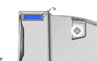
| (d) Install the No. 5 rocker panel moulding protector as shown in the illustration. HINT: Press the No. 5 rocker panel moulding protector firmly to install it. |
|
2. INSTALL NO. 4 ROCKER PANEL MOULDING PROTECTOR
HINT:
When installing the No. 4 rocker panel moulding protector, heat the body rocker panel moulding assembly using a heat light.
Heating Temperature| Item | Temperature |
|---|---|
| Body Rocker Panel Moulding Assembly | 20 to 30°C (68 to 86°F) |
CAUTION:
- Do not touch the heat light and heated parts, touching the heat light may result in burns.
- Touching heated parts for a long time may result in burns.
| *a | Heated Part |
| *b | Heat Light |
NOTICE:
Do not heat the body rocker panel moulding assembly excessively.
(a) Clean the body rocker panel moulding assembly.
(1) Using a heat light, heat the body rocker panel moulding assembly surface.
(2) Remove any remaining double-sided tape from the body rocker panel moulding assembly.
(3) Wipe off any tape adhesive residue with cleaner.
(b) Using a brush or felt, apply primer or equivalent to the No. 4 rocker panel moulding protector installation area.
NOTICE:
- Use a clean brush or felt.
- Do not touch the body rocker panel moulding assembly until the primer has dried.
(c) Remove the release paper from a new No. 4 rocker panel moulding protector.
HINT:
After removing the release paper, keep the exposed adhesive free from foreign matter.
| (d) Install the No. 4 rocker panel moulding protector. HINT: Press the No. 4 rocker panel moulding protector firmly to install it. |
|
.png)
READ NEXT:
 Installation
INSTALLATION CAUTION / NOTICE / HINT HINT:
Use the same procedure for the RH side and LH side.
The following procedure is for the LH side.
PROCEDURE 1. INSTALL BODY ROCKER PANEL MOULDING ASSEM
Roof Drip Side Finish Moulding
ComponentsCOMPONENTS ILLUSTRATION *1 CENTER ROOF DRIP SIDE FINISH MOULDING *2 NO. 1 ROOF DRIP SIDE FINISH MOULDING CLIP ● Non-reusable part - - RemovalREMOVAL CAUTION / NOTI
SEE MORE:
Components
COMPONENTS ILLUSTRATION *A for Driver Side *B for Front Passenger Side *1 COURTESY LIGHT ASSEMBLY *2 FRONT DOOR TRIM BOARD SUB-ASSEMBLY *3 MULTIPLEX NETWORK MASTER SWITCH ASSEMBLY WITH FRONT DOOR UPPER ARMREST BASE PANEL *4 NO. 2 DOOR TRIM PAD *5 POWER WINDOW REGU
Parts Location
PARTS LOCATION ILLUSTRATION *1 FUEL LID LOCK WITH MOTOR ASSEMBLY *2 FUEL LID OPENER SWITCH *3 INSTRUMENT PANEL JUNCTION BLOCK ASSEMBLY - FUEL OPN RELAY *4 NO. 1 ENGINE ROOM RELAY BLOCK AND NO. 1 JUNCTION BLOCK ASSEMBLY - FUEL OPN FUSE *5 TRUNK AND FUEL SWITCH ASSEMBLY -
