Lexus ES: Removal
REMOVAL
CAUTION / NOTICE / HINT
The necessary procedures (adjustment, calibration, initialization, or registration) that must be performed after parts are removed and installed, or replaced during grille shutter removal/installation are shown below.
Necessary Procedure After Parts Removed/Installed/Replaced| Replaced Part or Performed Procedure | Necessary Procedure | Effect/Inoperative Function when Necessary Procedure not Performed | Link |
|---|---|---|---|
| Front television camera view adjustment | Panoramic View Monitor System (for HV Model) | |
| Front bumper assembly |
|
| |
| Change grille shutter control mode and/or perform initialization | Grille Shutter system | |
PROCEDURE
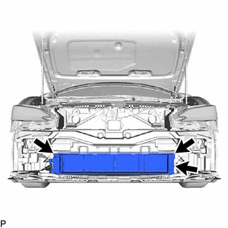
1. REMOVE FRONT BUMPER ASSEMBLY
Click here .gif)
2. REMOVE FRONT RADIATOR SIDE AIR GUIDE PLATE LH
| (a) Disengage the 2 claws to remove the front radiator side air guide plate LH. |
|
3. REMOVE FRONT RADIATOR SIDE AIR GUIDE PLATE RH
| (a) Disengage the 2 claws to remove the front radiator side air guide plate RH. |
|
4. REMOVE THERMISTOR ASSEMBLY
Click here
5. REMOVE RADIATOR SHUTTER SUB-ASSEMBLY
| (a) Disconnect the connector. |
|
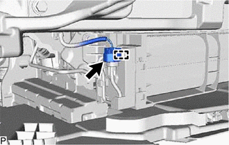
(b) Disengage the clamp.
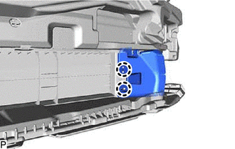
| (c) Remove the 3 bolts. |
|
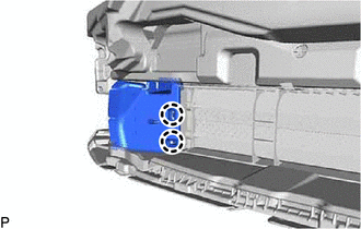
(d) Disengage the 2 guides to remove the radiator shutter sub-assembly as shown in the illustration.
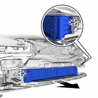
.png) | Remove in this Direction |
READ NEXT:
 Disassembly
DISASSEMBLY PROCEDURE 1. REMOVE MOTOR COVER (a) Disconnect the connector. (b) Disengage the 2 clamps. (c) Disengage the 4 claws to remove the motor cover as shown in the illustration.
Reassembly
REASSEMBLY PROCEDURE 1. INSTALL NO. 2 RADIATOR GRILLE SEAL HINT: When installing the No. 2 radiator grille seal, heat the radiator shutter using a heat light. Heating Temperature Item Temperature
Installation
INSTALLATION PROCEDURE 1. INSTALL RADIATOR SHUTTER SUB-ASSEMBLY (a) Engage the 2 guides as shown in the illustration. Install in this Direction (b) Install the radiator shutter sub-assembly
SEE MORE:
Parts Location
PARTS LOCATION ILLUSTRATION *1 FRONT DOOR COURTESY LIGHT SWITCH ASSEMBLY (for LH) *2 FRONT DOOR COURTESY LIGHT SWITCH ASSEMBLY (for RH) *3 ROOF SUNSHADE ECU (SLIDING ROOF DRIVE GEAR ASSEMBLY) *4 SLIDING ROOF ECU (SLIDING ROOF DRIVE GEAR ASSEMBLY) *5 COMBINATION METER ASSEMB
Airbag Signal Signal Plausibility Failure (B15C464)
DESCRIPTION If the DCM (telematics transceiver) detects an error in communication between the DCM (telematics transceiver) and the airbag ECU assembly as a result of the DCM (telematics transceiver) self check, this DTC will be set. DTC No. Detection Item DTC Detection Condition Trouble Are
