Lexus ES: Installation
Lexus ES (XZ10) Service Manual / Vehicle Interior / Exterior Panels / Trim / Grille Shutter / Installation
INSTALLATION
PROCEDURE
1. INSTALL RADIATOR SHUTTER SUB-ASSEMBLY
(a) Engage the 2 guides as shown in the illustration.
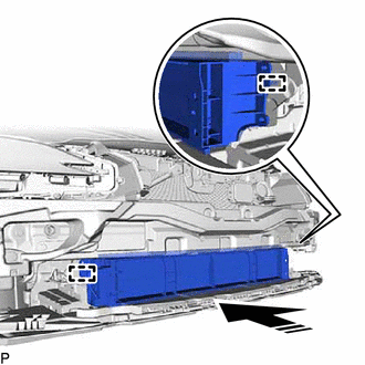
.png) | Install in this Direction |
(b) Install the radiator shutter sub-assembly with the 3 bolts.
Torque:
5.5 N·m {56 kgf·cm, 49 in·lbf}
(c) Engage the clamp.
(d) Connect the connector.
2. INSTALL THERMISTOR ASSEMBLY
Click here .gif)
3. INSTALL FRONT RADIATOR SIDE AIR GUIDE PLATE RH
(a) Engage the 2 claws to install the front radiator side air guide plate RH.
4. INSTALL FRONT RADIATOR SIDE AIR GUIDE PLATE LH
(a) Engage the 2 claws to install the front radiator side air guide plate LH.
5. INSTALL FRONT BUMPER ASSEMBLY
Click here
READ NEXT:
 Precaution
PRECAUTION PRECAUTION FOR DISCONNECTING CABLE FROM NEGATIVE AUXILIARY BATTERY TERMINAL NOTICE: When disconnecting the cable from the negative (-) auxiliary battery terminal, initialize the following s
Parts Location
PARTS LOCATION ILLUSTRATION *1 SWING GRILLE ACTUATOR ASSEMBLY *2 RADIATOR SHUTTER SUB-ASSEMBLY *3 ECM - - ILLUSTRATION *1 COMBINATION METER ASSEMBLY *2 INSTRUMENT PANE
SEE MORE:
Side Camera LH Response Malfunction (C2A6B)
DESCRIPTION During self diagnosis of the parking assist ECU, the parking assist ECU sends display mode ID signals to the side television camera assembly LH. This DTC is stored when the output of the side television camera assembly LH does not match the expected output. DTC No. Detection Item
System Description
SYSTEM DESCRIPTION POWER WINDOW CONTROL SYSTEM DESCRIPTION (a) The power window control system controls the power window operation using the power window regulator motor assemblies. The main controls of this system are the multiplex network master switch assembly (mounted on the driver door), power
© 2016-2026 Copyright www.lexguide.net
