Lexus ES: Removal
REMOVAL
CAUTION / NOTICE / HINT
The necessary procedures (adjustment, calibration, initialization, or registration) that must be performed after parts are removed and installed, or replaced during outer rear view mirror assembly with cover removal/installation are shown below.
Necessary Procedure After Parts Removed/Installed/Replaced (for Gasoline Model)| Replaced Part or Performed Procedure | Necessary Procedure | Effect/Inoperative Function when Necessary Procedure not Performed | Link |
|---|---|---|---|
| Side television camera view adjustment | Panoramic view monitor system | |
| Replaced Part or Performed Procedure | Necessary Procedure | Effect/Inoperative Function when Necessary Procedure not Performed | Link |
|---|---|---|---|
| Side television camera view adjustment | Panoramic view monitor system | |
HINT:
- Use the same procedure for the RH side and LH side.
- The following procedure is for the LH side.
PROCEDURE
1. REMOVE OUTER MIRROR
Click here .gif)
2. REMOVE OUTER MIRROR COVER ASSEMBLY
(a) w/o Panoramic View Monitor System:
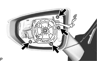
(1) Remove the 4 screws.
(2) Pull the outer mirror cover assembly as shown in the illustration to disengage the 2 claws.
NOTICE:
As the claws may be damaged, make sure not to apply force in any direction other than shown in the illustration.
HINT:
If it is difficult to disengage the claws, disengage them using a screwdriver with its tip wrapped with protective tape.
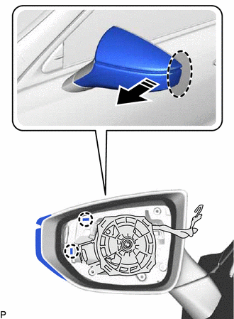
.png) | Place Hand Here |
.png) | Pull in this Direction |
(3) Pull the outer mirror cover assembly as shown in the illustration to disengage the 2 claws.
NOTICE:
As the claws may be damaged, make sure not to apply force in any direction other than shown in the illustration.
HINT:
If it is difficult to disengage the claws, disengage them using a screwdriver with its tip wrapped with protective tape.
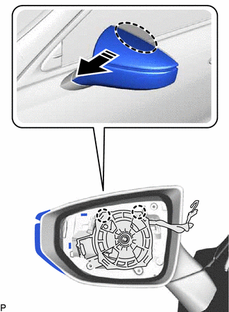
| | Place Hand Here |
| | Pull in this Direction |
(4) Pull the outer mirror cover assembly as shown in the illustration to disengage the claw and remove the outer mirror cover assembly.
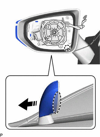
| | Place Hand Here |
| | Remove in this Direction |
NOTICE:
As the claws may be damaged, make sure not to apply force in any direction other than shown in the illustration.
HINT:
If it is difficult to disengage the claws, disengage them using a screwdriver with its tip wrapped with protective tape.
| (5) Disconnect the connector to remove the outer mirror cover assembly. |
|
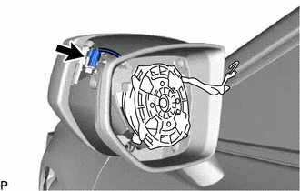
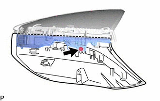
(b) w/ Panoramic View Monitor System:
(1) Remove the 4 screws.
(2) Pull the outer mirror cover assembly as shown in the illustration to disengage the 2 claws.
NOTICE:
As the claws may be damaged, make sure not to apply force in any direction other than shown in the illustration.
HINT:
If it is difficult to disengage the claws, disengage them using a screwdriver with its tip wrapped with protective tape.
| | Place Hand Here |
| | Pull in this Direction |
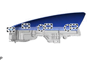
(3) Pull the outer mirror cover assembly as shown in the illustration to disengage the 2 claws.
NOTICE:
As the claws may be damaged, make sure not to apply force in any direction other than shown in the illustration.
HINT:
If it is difficult to disengage the claws, disengage them using a screwdriver with its tip wrapped with protective tape.
| | Place Hand Here |
| | Pull in this Direction |
(4) Pull the outer mirror cover assembly as shown in the illustration to disengage the claw and remove the outer mirror cover assembly.
NOTICE:
As the claws may be damaged, make sure not to apply force in any direction other than shown in the illustration.
HINT:
If it is difficult to disengage the claws, disengage them using a screwdriver with its tip wrapped with protective tape.
| | Place Hand Here |
| | Pull in this Direction |
| (5) Disconnect the connector. |
|
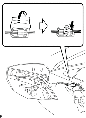
(6) Disengage the clamp as shown in the illustration.
| | Remove in this Direction |
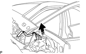
(7) Remove the outer mirror tape as shown in the illustration.
| | Remove in this Direction |
(8) Disengage the 2 claws to remove the camera connector clamp.
| (9) Insert a 0.9 mm (0.0354 in.) spark plug gap gauge or similar tool into the connector as shown in the illustration. NOTICE:
|
|
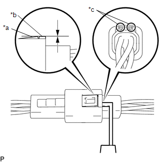
(10) Lift the claw and disconnect the connector.
3. REMOVE SIDE TELEVISION CAMERA ASSEMBLY (w/ Panoramic View Monitor System)
Click here
4. REMOVE OUTER MIRROR LOWER COVER
| (a) Remove the screw and outer mirror lower cover. |
|
5. REMOVE OUTER MIRROR UPPER COVER
| (a) Disengage the 2 claws and 4 guides to remove the outer mirror upper cover from the side turn signal light assembly. |
|
6. REMOVE VISOR COVER ASSEMBLY
(a) Remove the visor cover assembly from the outer mirror actuator assembly.
READ NEXT:
 Installation
INSTALLATION CAUTION / NOTICE / HINT HINT:
Use the same procedure for the RH side and LH side.
The following procedure is for the LH side.
PROCEDURE 1. INSTALL VISOR COVER ASSEMBLY (a) Install
Components
COMPONENTS ILLUSTRATION *1 OUTER MIRROR - -
SEE MORE:
Electric Parking Brake does not Operate
WIRING DIAGRAM CAUTION / NOTICE / HINT NOTICE:
Inspect the fuses for circuits related to this system before performing the following procedure.
The electric parking brake may still operate up to 20 seconds after the power switch is turned off. Before disconnecting connectors or fuses, turn the
Installation
INSTALLATION PROCEDURE 1. INSTALL MASS AIR FLOW METER SUB-ASSEMBLY HINT: Perform "Inspection After Repair" after replacing the mass air flow meter sub-assembly. Click here (a) Install the mass air flow meter sub-assembly to the air cleaner cap sub-assembly with the 2 screws. NOTICE:
If the mas
