Lexus ES: Installation
INSTALLATION
CAUTION / NOTICE / HINT
HINT:
- Use the same procedure for the RH side and LH side.
- The following procedure is for the LH side.
PROCEDURE
1. INSTALL VISOR COVER ASSEMBLY
(a) Install the visor cover assembly to the outer mirror actuator assembly.
2. INSTALL OUTER MIRROR UPPER COVER
(a) Engage the 4 guides and 2 claws to install the outer mirror upper cover to the side turn signal light assembly.
3. INSTALL OUTER MIRROR LOWER COVER
(a) Install outer mirror lower cover with the screw.
4. INSTALL SIDE TELEVISION CAMERA ASSEMBLY (w/ Panoramic View Monitor System)
Click here .gif)
5. INSTALL OUTER MIRROR COVER ASSEMBLY
(a) w/o Panoramic View Monitor System:
(1) Connect the connector.
(2) Engage the 5 claws as shown in the illustration.
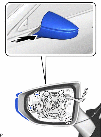
.png) | Install in this Direction |
(3) Install the outer mirror cover assembly with the 4 screws.
(b) w/ Panoramic View Monitor System:
(1) Connect the connector.
(2) Connect the side television camera connector.
| (3) Engage the 2 claws as shown in the illustration to install the camera connector clamp. |
|
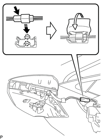
(4) Paste a new outer mirror tape around the camera connector clamp.
(5) Engage the clamp.
(6) Engage the 5 claws as shown in the illustration.
| | Install in this Direction |
(7) Install the outer mirror cover assembly with the 4 screws.
6. INSTALL OUTER MIRROR
Click here
7. PERFORM CALIBRATION (w/ Panoramic View Monitor System)
for Gasoline Model: Click here
for HV Model: Click here
READ NEXT:
 Components
COMPONENTS ILLUSTRATION *1 OUTER MIRROR - -
Removal
REMOVAL CAUTION / NOTICE / HINT HINT:
Use the same procedure for the RH side and LH side.
The following procedure is for the LH side.
PROCEDURE 1. REMOVE OUTER MIRROR (a) Apply protective tape
SEE MORE:
Front Passenger Side Power Mirror cannot be Adjusted with Power Mirror Switch
DESCRIPTION The outer mirror switch assembly sends the mirror adjust switch signals to the main body ECU (multiplex network body ECU). The main body ECU (multiplex network body ECU) then sends the received mirror adjust switch signals to the outer mirror control ECU assembly (front passenger door) v
Installation
INSTALLATION PROCEDURE 1. INSTALL REAR ENGINE OIL SEAL (a) Using height adjustment attachments and plate lift attachments, place the engine assembly on a flat level surface. NOTICE:
Using height adjustment attachments and plate lift attachments, keep the engine assembly level.
To prevent the No
