Lexus ES: Removal
REMOVAL
CAUTION / NOTICE / HINT
The necessary procedures (adjustment, calibration, initialization, or registration) that must be performed after parts are removed and installed, or replaced during back-up battery removal/installation are shown below.
Necessary Procedure After Parts Removed/Installed/Replaced (for HV Model)| Replaced Part or Performed Procedure | Necessary Procedure | Effect/Inoperative Function when Necessary Procedure not Performed | Link |
|---|---|---|---|
| Back-up battery | Perform the reset back-up battery condition | Safety Connect System | |
| Replaced Part or Performed Procedure | Necessary Procedure | Effect/Inoperative Function when Necessary Procedure not Performed | Link |
|---|---|---|---|
| Back-up battery | Perform the reset back-up battery condition | Safety Connect System | |
PROCEDURE
1. REMOVE DCM (TELEMATICS TRANSCEIVER) WITH BRACKET
Click here .gif)
2. REMOVE BACK-UP BATTERY
(a) Disengage the 3 claws and 2 guides as shown in the illustration to remove the transceiver cover.
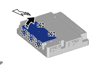
.png) | Remove in this Direction (1) |
.png) | Remove in this Direction (2) |
(b) Disconnect the connector.
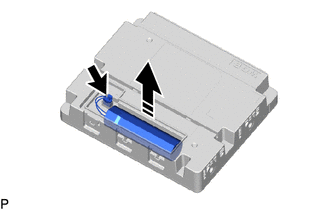
| | Remove in this Direction |
(c) Remove the back-up battery as shown in the illustration.
READ NEXT:
 Components
COMPONENTS ILLUSTRATION *1 CENTER INSTRUMENT CLUSTER FINISH PANEL SUB-ASSEMBLY *2 INSTRUMENT PANEL FINISH PANEL END LH *3 INSTRUMENT PANEL FINISH PANEL END RH *4 REAR UPPER CONSOLE
Installation
INSTALLATION PROCEDURE 1. INSTALL DCM (TELEMATICS TRANSCEIVER) 2. INSTALL NO. 1 TELEPHONE BRACKET (a) Install the No. 1 telephone bracket with the screw. 3. INSTALL TELEPHONE BRACKET (a) Install the t
SEE MORE:
Brake Hold
The brake hold system keeps the
brake applied when the shift lever is
in D, S or N with the system on and
the brake pedal has been
depressed to stop the vehicle. The
system releases the brake when the
accelerator pedal is depressed with
the shift lever in D or S to allow
smooth start off.
E
Hybrid/EV Battery Precharge Contactor Circuit Short to Ground (P0AE411)
DESCRIPTION The SMRs (System Main Relays) are the relays that connect or disconnect the high-voltage system in accordance with commands from the hybrid vehicle control ECU. There are 3 SMRs and 1 system main resistor. SMRB, SMRP, SMRG and the system main resistor are located in the HV battery juncti
