Lexus ES: Installation
INSTALLATION
PROCEDURE
1. INSTALL DCM (TELEMATICS TRANSCEIVER)
2. INSTALL NO. 1 TELEPHONE BRACKET
(a) Install the No. 1 telephone bracket with the screw.
3. INSTALL TELEPHONE BRACKET
(a) Install the telephone bracket with the screw.
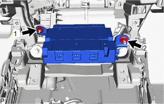
4. INSTALL DCM (TELEMATICS TRANSCEIVER) WITH BRACKET
(a) Connect each connector.
| (b) Install the DCM (telematics transceiver) with bracket with the 2 nuts. Torque: 14 N·m {143 kgf·cm, 10 ft·lbf} HINT: Install the nuts in the order shown in the illustration. |
|
5. INSTALL RADIO RECEIVER ASSEMBLY WITH SWITCH
Click here .gif)
6. INSTALL LOWER INSTRUMENT PANEL SUB-ASSEMBLY
Click here
7. INSTALL LOWER INSTRUMENT PANEL LH
Click here
8. INSTALL NO. 2 INSTRUMENT PANEL UNDER COVER SUB-ASSEMBLY
Click here
9. INSTALL INSTRUMENT SIDE PANEL RH
Click here
10. INSTALL FRONT DOOR OPENING TRIM COVER RH
HINT:
Use the same procedure as for the LH side.
Click here
11. INSTALL COWL SIDE TRIM BOARD RH
HINT:
Use the same procedure as for the LH side.
Click here
12. INSTALL FRONT DOOR SCUFF PLATE RH
HINT:
Use the same procedure as for the LH side.
Click here
13. INSTALL LOWER INSTRUMENT PANEL
Click here
14. INSTALL UPPER CONSOLE PANEL SUB-ASSEMBLY
Click here
15. INSTALL REAR UPPER CONSOLE PANEL SUB-ASSEMBLY
Click here
16. INSTALL SHIFT LEVER KNOB SUB-ASSEMBLY
for UA80E: Click here
for P710: Click here
17. INSTALL CENTER INSTRUMENT CLUSTER FINISH PANEL SUB-ASSEMBLY
Click here
18. INSTALL INSTRUMENT PANEL FINISH PANEL END RH
Click here
19. INSTALL INSTRUMENT PANEL FINISH PANEL END LH
Click here
20. PERFORM DCM ACTIVATION
HINT:
After replacing the DCM (telematics transceiver), make sure to perform DCM activation.
for HV Model: Click here
for Gasoline Model: Click here
21. PERFORM REGISTRATION
*: for Lexus Enform Remote Compatible Type
HINT:
After replacing the DCM (telematics transceiver), make sure to perform code registration (Smart access system with push-button start (for Start Function)).
for HV Model: Click here
for Gasoline Model: Click here
READ NEXT:
 Installation
INSTALLATION PROCEDURE 1. INSTALL DCM (TELEMATICS TRANSCEIVER) 2. INSTALL NO. 1 TELEPHONE BRACKET (a) Install the No. 1 telephone bracket with the screw. 3. INSTALL TELEPHONE BRACKET (a) Install the t
Removal
REMOVAL CAUTION / NOTICE / HINT The necessary procedures (adjustment, calibration, initialization, or registration) that must be performed after parts are removed and installed, or replaced during DCM
Removal
REMOVAL CAUTION / NOTICE / HINT The necessary procedures (adjustment, calibration, initialization, or registration) that must be performed after parts are removed and installed, or replaced during DCM
SEE MORE:
Lost Communication with Front Shade Module (B2346)
DESCRIPTION This DTC is stored when LIN communication between the sliding roof ECU (sliding roof drive gear assembly) and roof sunshade ECU (sliding roof drive gear assembly) stops for 10 seconds or more. DTC No. Detection Item DTC Detection Condition Trouble Area B2346 Lost Communica
Hybrid/EV Battery Air Temperature Sensor "A" Circuit Short to Ground (P0AAC11,P0AAC15)
DESCRIPTION The inlet air temperature sensor (battery) is mounted on the HV battery. The resistance of the sensor varies in accordance with changes in the intake air temperature. The characteristics of the inlet air temperature sensor are the same as those of the battery temperature sensors (Click h
