Lexus ES: System Diagram
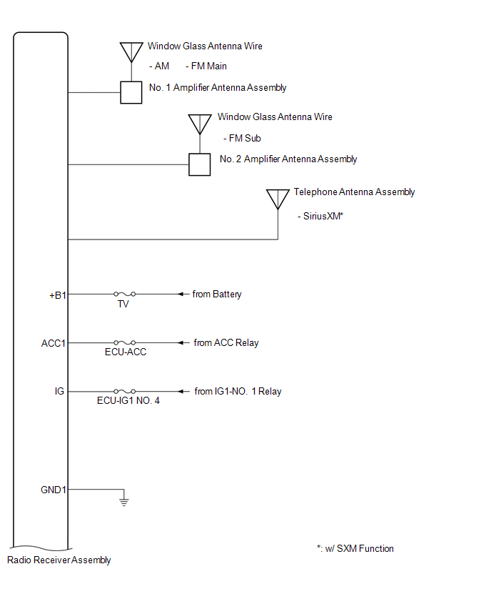
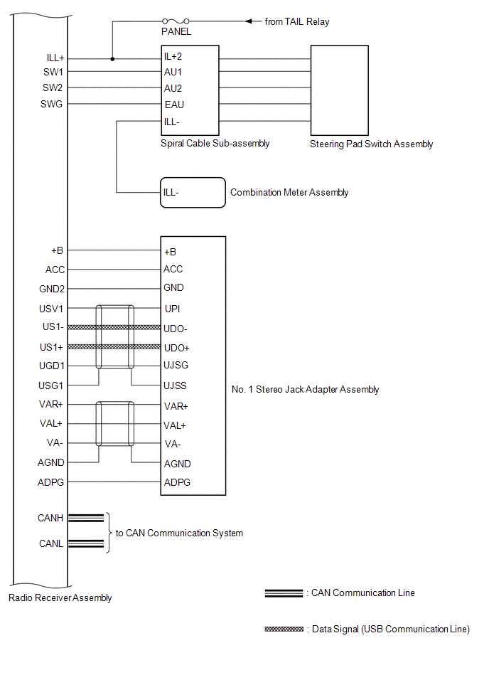
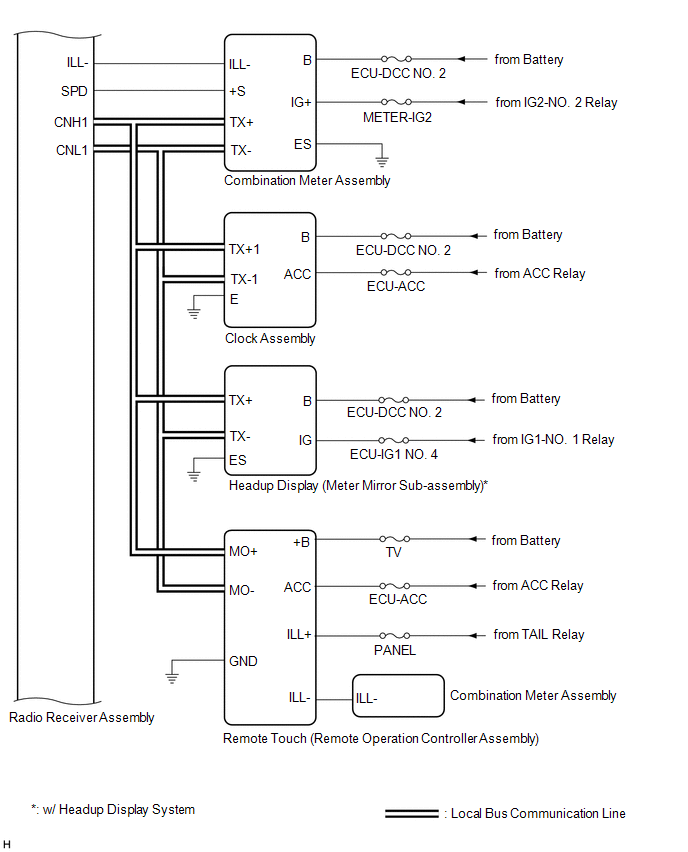
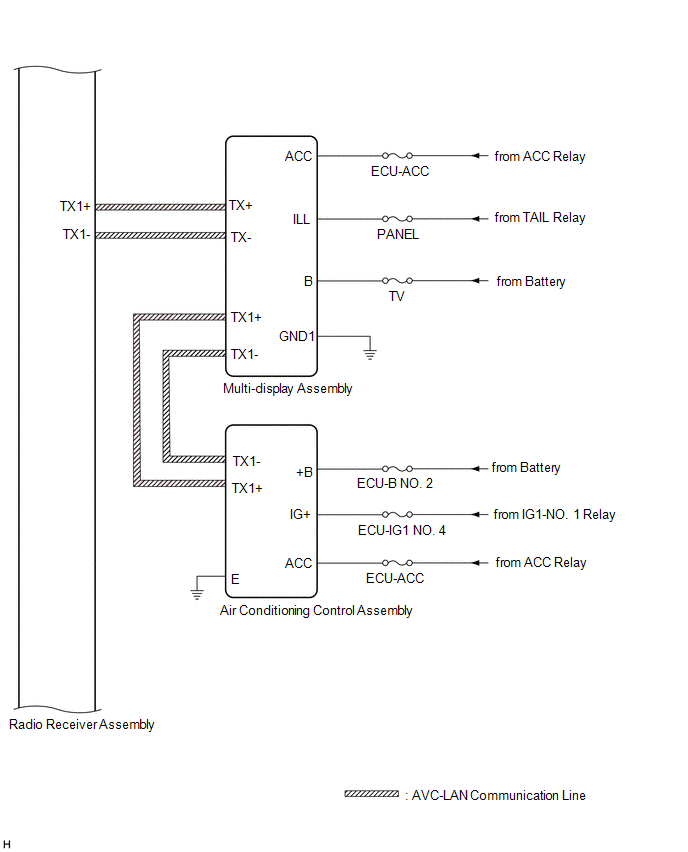
SYSTEM DIAGRAM
 w/ Parking Assist Monitor System
 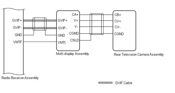 w/ Panoramic View Monitor System
 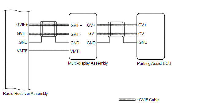 w/o Manual (SOS) Switch
 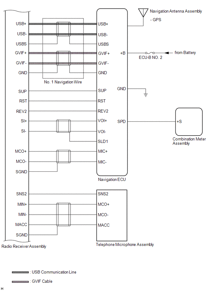 w/ Manual (SOS) Switch
 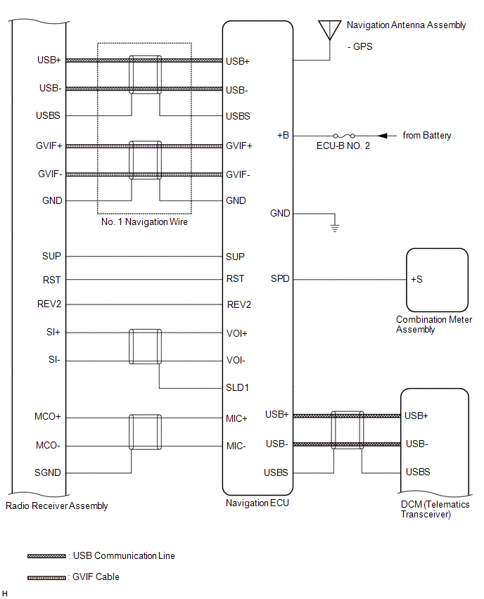 w/ Manual (SOS) Switch
 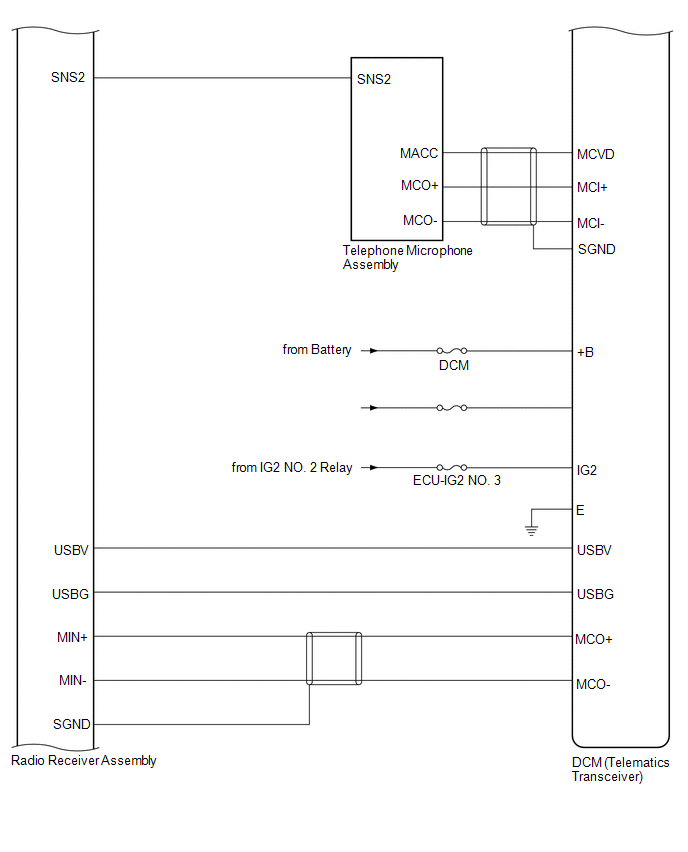 for 10 Speakers
 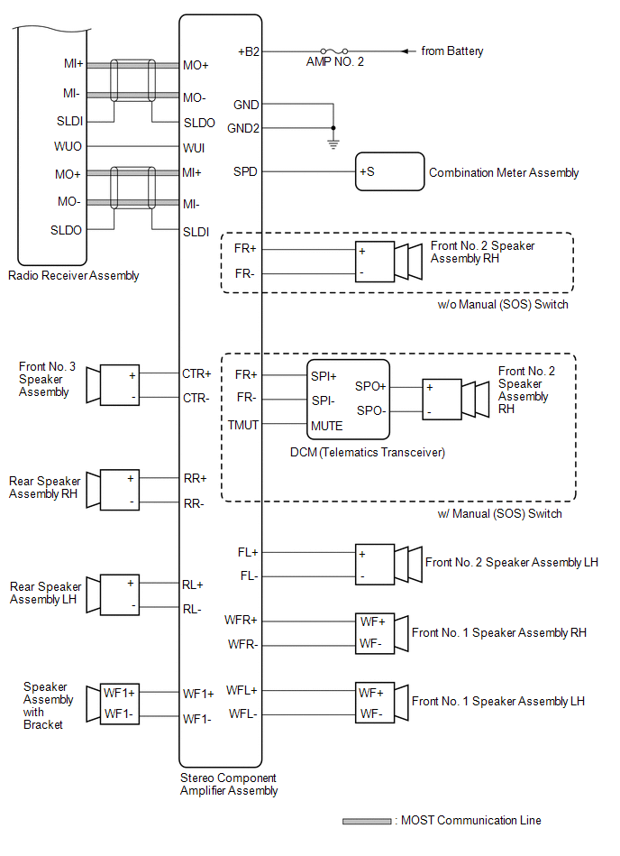 for 17 Speakers
 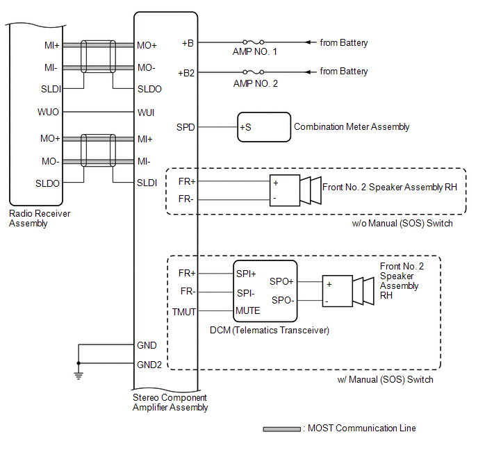 for 17 Speakers
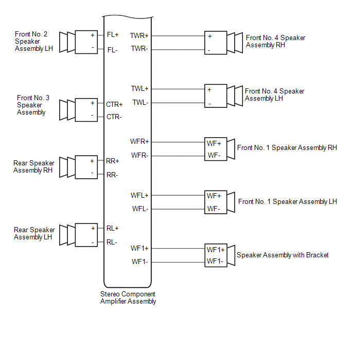
READ NEXT:
 System Diagram
SYSTEM DIAGRAM w/ Parking Assist Monitor System w/ Panoramic View Monitor System w/o Manual (SOS) Switch w/ Manual (SOS) Switch w/ Manual (SOS) Switch for 10 Speakers for 17 Speakers for 17
Terminals Of Ecu
TERMINALS OF ECU HINT: Check from the rear of the connector while it is connected to the components. RADIO RECEIVER ASSEMBLY Terminal No. (Symbol) Wiring Color Terminal Description Condition
Sending Malfunction (Navigation to APGS) (U0073,U0100,U0129,U0140,U0155,U0164,U0198,U023B,U0265,U1110)
DESCRIPTION These DTCs are stored when a malfunction occurs in the CAN communication circuit. DTC No. Detection Item DTC Detection Condition Trouble Area U0073 Sending Malfunction (Navi
SEE MORE:
Vehicle Speed Signal Circuit between Navigation ECU and Combination Meter
DESCRIPTION The navigation ECU receives a vehicle speed signal from the combination meter assembly. HINT:
A voltage of 12 V or 5 V is output from each ECU and then input to the combination meter assembly. The signal is changed to a pulse signal at the transistor in the combination meter assembly.
Drive Motor "A" Phase U Current Sensor Signal Bias Level Out of Range / Zero Adjustment Failure (P0BE528,...,P0BED28)
DTC SUMMARY MALFUNCTION DESCRIPTION These DTCs indicate that the current sensor value is abnormal. The cause of this malfunction may be one of the following: Internal inverter malfunction
Current sensor malfunction
Inverter with converter assembly internal circuit malfunction
DESCRIPTION The
© 2016-2026 Copyright www.lexguide.net
