Lexus ES: Components
COMPONENTS
ILLUSTRATION
.png)
| *1 | CENTER INSTRUMENT CLUSTER FINISH PANEL SUB-ASSEMBLY | *2 | INSTRUMENT PANEL FINISH PANEL END LH |
| *3 | INSTRUMENT PANEL FINISH PANEL END RH | *4 | REAR UPPER CONSOLE PANEL SUB-ASSEMBLY |
| *5 | SHIFT LEVER KNOB SUB-ASSEMBLY | *6 | UPPER CONSOLE PANEL SUB-ASSEMBLY |
ILLUSTRATION
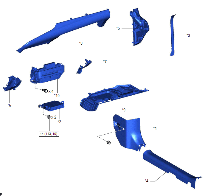
| *1 | COWL SIDE TRIM BOARD RH | *2 | DCM (TELEMATICS TRANSCEIVER) WITH BRACKET |
| *3 | FRONT DOOR OPENING TRIM COVER RH | *4 | FRONT DOOR SCUFF PLATE RH |
| *5 | INSTRUMENT SIDE PANEL RH | *6 | LOWER INSTRUMENT PANEL |
| *7 | LOWER INSTRUMENT PANEL LH | *8 | LOWER INSTRUMENT PANEL SUB-ASSEMBLY |
| *9 | NO. 2 INSTRUMENT PANEL UNDER COVER SUB-ASSEMBLY | *10 | RADIO RECEIVER ASSEMBLY WITH SWITCH |
.png) | N*m (kgf*cm, ft.*lbf) : Specified torque | - | - |
ILLUSTRATION
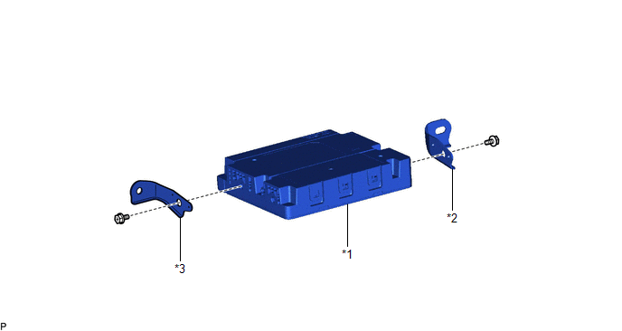
| *1 | DCM (TELEMATICS TRANSCEIVER) | *2 | NO. 1 TELEPHONE BRACKET |
| *3 | TELEPHONE BRACKET | - | - |
READ NEXT:
 Installation
INSTALLATION PROCEDURE 1. INSTALL DCM (TELEMATICS TRANSCEIVER) 2. INSTALL NO. 1 TELEPHONE BRACKET (a) Install the No. 1 telephone bracket with the screw. 3. INSTALL TELEPHONE BRACKET (a) Install the t
Installation
INSTALLATION PROCEDURE 1. INSTALL DCM (TELEMATICS TRANSCEIVER) 2. INSTALL NO. 1 TELEPHONE BRACKET (a) Install the No. 1 telephone bracket with the screw. 3. INSTALL TELEPHONE BRACKET (a) Install the t
Removal
REMOVAL CAUTION / NOTICE / HINT The necessary procedures (adjustment, calibration, initialization, or registration) that must be performed after parts are removed and installed, or replaced during DCM
SEE MORE:
Terminals Of Ecu
TERMINALS OF ECU CHECK ECM HINT: As a waterproof connector is used for the ECM, voltage, resistance and waveform inspections cannot be performed. The voltage, resistance and waveform values are provided for reference only. Terminal No. (Symbol) Wiring Color Terminal Description Condition
Components
COMPONENTS ILLUSTRATION *1 ENGINE WATER PUMP ASSEMBLY (WATER INLET HOUSING) *2 GASKET N*m (kgf*cm, ft.*lbf): Specified torque ● Non-reusable part
© 2016-2026 Copyright www.lexguide.net
